
Test method and device for electric locomotive control cabinet

A technology for electric locomotives and test devices, applied in general control systems, control/regulation systems, radio wave measurement systems, etc., can solve problems such as unfavorable on-site user application, data loss, unfavorable maintenance, etc., and achieve easy portability and versatility , easy to maintain and upgrade, and the effect of meeting real-time requirements

Active Publication Date: 2021-04-16
HUNAN VOCATIONAL COLLEGE OF RAILWAY TECH
View PDF4 Cites 0 Cited by
  • Summary
  • Abstract
  • Description
  • Claims
  • Application Information

AI Technical Summary

Problems solved by technology

Generally speaking, the RAM area in the DSP chip is only 64K, and the storage space required by a motor model is about 30K, so it cannot meet the requirements for storing multiple motor models. In addition, the RAM area of ​​​​the DSP chip is a volatile storage space, that is, The data in the RAM area will be lost after power failure, which is not conducive to the application of on-site users
The size of the Flash storage area outside the DSP chip is generally 512K. Although it can meet the storage space requirements of multiple motor models to a certain extent, if all the motor models are written into the Flash area, it will be difficult for the maintenance and function of the later test equipment. Expansion brings inconvenience
For example, the user of a locomotive depot test bench only needs 5 types of locomotive electronic cabinet motor models, while another locomotive depot test bench user needs 8 types of locomotive electronic cabinet motor models. If different motor model libraries are programmed in the Flash area, is not conducive to unified maintenance
Even for users of the same test bench, if it involves function expansion, professionals must use professional tools to rewrite the Flash program, which leads to low work efficiency and high cost

Method used


Image

  • Test method and device for electric locomotive control cabinet
  • Test method and device for electric locomotive control cabinet

Examples


Embodiment Construction

[0053] In order to make the purposes, technical solutions and advantages of the embodiments of the present invention clearer, the technical solutions in the embodiments of the present invention will be clearly and completely described below with reference to the accompanying drawings in the embodiments of the present invention. Obviously, the described embodiments These are some embodiments of the present invention, but not all of them. Based on the embodiments of the present invention, all other embodiments obtained by those of ordinary skill in the art without creative efforts shall fall within the protection scope of the present invention.

[0054] Accordingly, the detailed descriptions of embodiments of the invention provided in the following drawings are not intended to limit the scope of the invention as claimed, but are merely representative of selected embodiments of the invention.

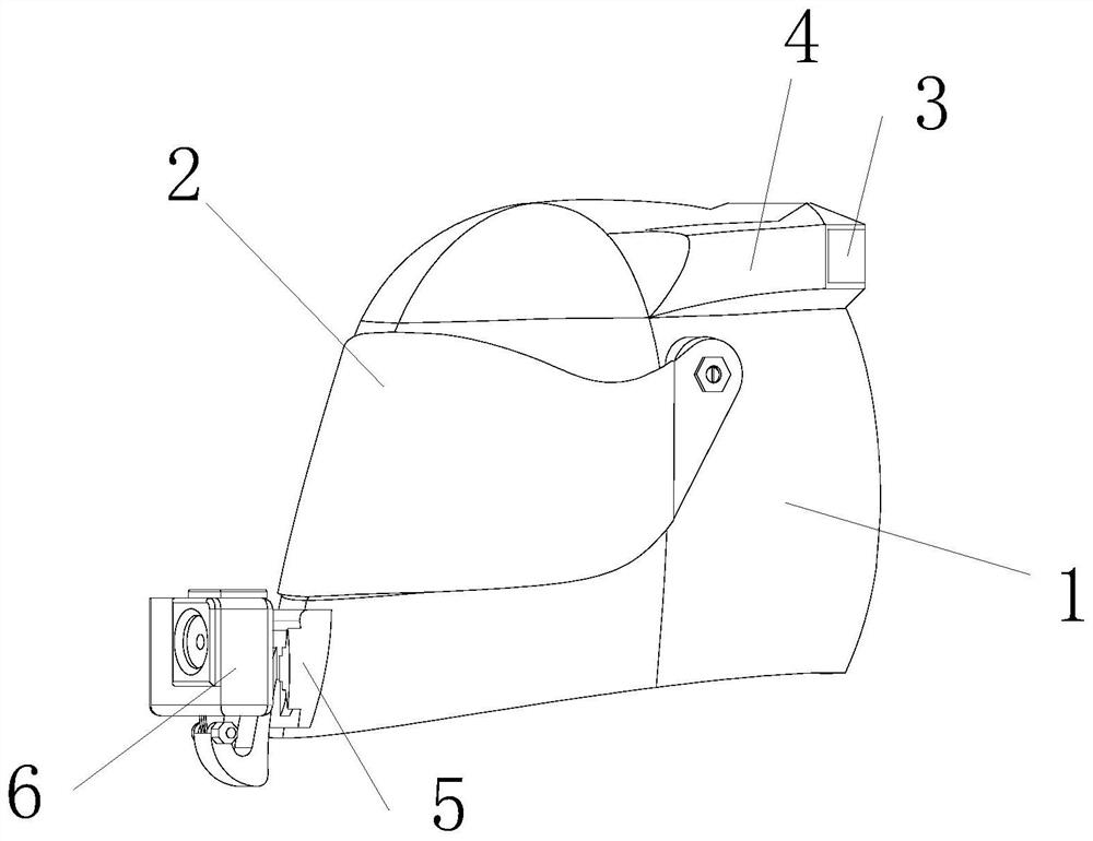
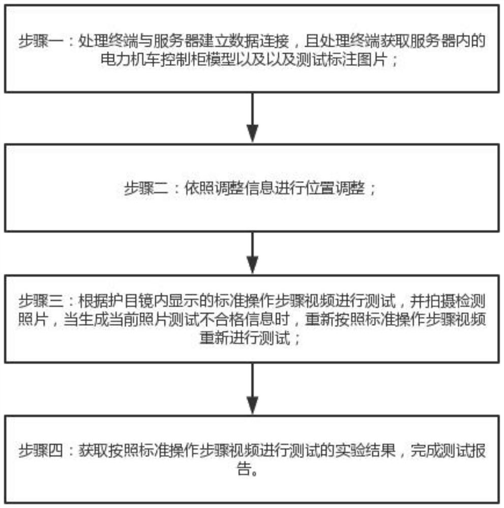
[0055] like Figure 1-2 As shown, a test device for an electric locomotive control ca...


PUM


Abstract

The invention discloses a test method and device for an electric locomotive control cabinet, belongs to the field of electric locomotives, and relates to the electric locomotive test technology. According to the technical scheme provided by the invention, the motor model is stored in the server in a non-test state, and the required motor model is dynamically downloaded into the test device for loading and testing through data transmission in the test process, so that the characteristic of large storage space of the server is fully utilized, the requirement of storing various motor models can be met, one testing device can be used for testing a plurality of electric locomotives; the selection right of the motor model does not consider the selection of the motor model in the design stage of the server and the test device, so that the test device can be uniformly designed even for electric locomotive control cabinet tests of different users, and different electric locomotive control cabinets have interchangeability. Therefore, the portability and the universality of the testing device are facilitated.

Description

technical field [0001] The invention belongs to the field of electric locomotives, and relates to a testing technology for electric locomotives, in particular to a testing method and device for a control cabinet of an electric locomotive. Background technique [0002] The electric locomotive control cabinet is an important part of the electric locomotive control system. Its main function is to realize the traction and braking control of the locomotive by controlling the state of the motor. Its performance and operating state directly affect the function of the electric locomotive control system. Therefore, an accurate test method is required to test the electric locomotive control cabinet. [0003] In the prior art, an electric locomotive control cabinet test device is usually used to simulate a motor model for testing. In the non-test state, store the motor model on the signal input and output hardware; during testing, run the motor model on the signal input and output har...

Claims


Application Information

Patent Timeline
Patent Type & Authority Applications(China)
IPC IPC(8): G05B23/00G01C11/04G01C11/36
Inventor 江利国颜泽玲江鹏
Owner HUNAN VOCATIONAL COLLEGE OF RAILWAY TECH
Learn More