Effective disinfection equipment for biomass energy steam box

A technology of biomass energy and disinfection equipment, which is applied in the direction of sanitary equipment for toilets, disinfection, construction, etc., and can solve the problems of bacterial impurities mixed in, no sterilization process, labor consumption, etc.

Pending Publication Date: 2021-04-16
陈湜尹
View PDF14 Cites 1 Cited by
  • Summary
  • Abstract
  • Description
  • Claims
  • Application Information

AI Technical Summary

Problems solved by technology

[0005] In order to overcome the disadvantages in the prior art that the hand-held atomizing nozzle moves, consumes manpower, and there is no further sterilization process, bacterial impurities may be mixed into the disinfectant, and the handholds are used to stabilize the closing block. The technical problem of the present invention is to provide an automatic omnidirectional spraying Disinfectant, use disinfection ultraviolet light to further sterilize, easily fix open and unlock and close the biomass energy steamer for effective disinfection equipment

Method used


Image

  • Effective disinfection equipment for biomass energy steam box
  • Effective disinfection equipment for biomass energy steam box
  • Effective disinfection equipment for biomass energy steam box

Examples


Embodiment 1

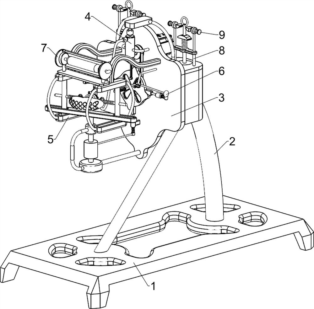
[0028] A kind of effective disinfection equipment for biomass energy steamer, such as figure 1 , figure 2 , image 3 , Figure 4 and Figure 5 As shown, it includes a base plate 1, a support frame 2, a mounting plate 3, a spraying mechanism 4, a swing mechanism 5 and a lifting mechanism 6. The support frame 2 is connected to the upper part of the base plate 1, and the mounting plate 3 is connected to the front side of the upper part of the support frame 2. A spraying mechanism 4 is arranged between the plate 3 and the upper part of the support frame 2 , a rocking mechanism 5 is arranged between the front side of the mounting plate 3 and the spraying mechanism 4 , and a lifting mechanism 6 is arranged between the front side of the mounting plate 3 and the rocking mechanism 5 .

[0029]The spraying mechanism 4 includes a servo motor 41, a transmission assembly 42, a turntable 43, a first connecting rod 44, a second connecting rod 45, a piston 46, a cylinder 47, a water tank ...

Embodiment 2

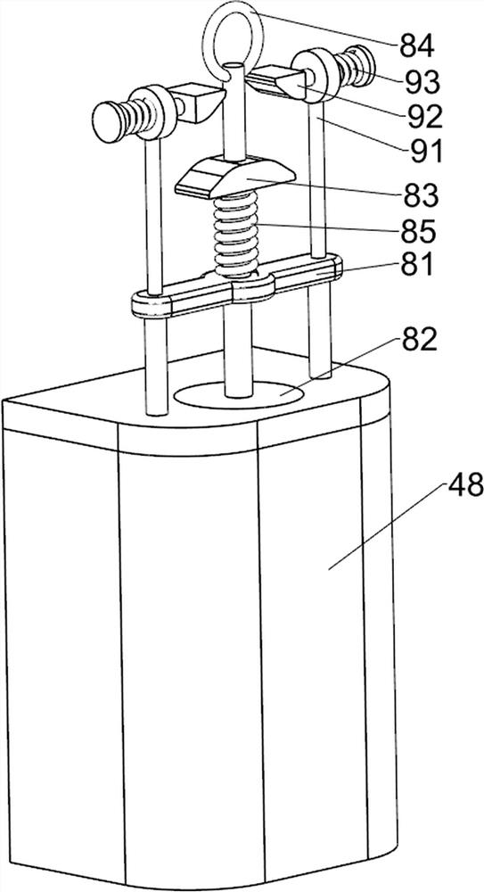
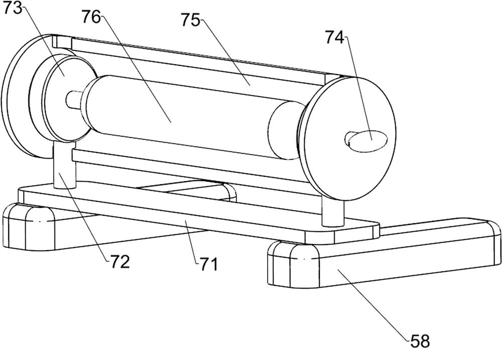
[0034] On the basis of Example 1, such as figure 1 , Figure 6 and Figure 7 Shown, also comprise ultraviolet lamp assembly 7, ultraviolet lamp assembly 7 comprises baffle plate 71, support column 72, connection block 73, turn handle 74, shield 75 and disinfection ultraviolet lamp 76, between the front side of chute seat 58 top A baffle 71 is connected between them, and the left and right sides of the upper part of the baffle 71 are connected with a support column 72, and the upper side of the support column 72 is connected with a connecting block 73, and a rotating handle 74 is connected between the connecting blocks 73, and the rotating handle 74 is left and right. A protective cover 75 is connected between the two sides, and a sterilizing ultraviolet lamp 76 is connected in the middle part of the handle 74 .

[0035] Turn on the disinfection ultraviolet lamp 76, and when the disinfectant solution is sprayed from the atomizing nozzle 413, turn the handle 74 clockwise to dr...


PUM


Abstract

The invention relates to disinfection equipment, in particular to effective disinfection equipment for a biomass energy steam box. According to the biomass energy steam box effective disinfection equipment, a disinfectant is automatically sprayed in all directions, sterilization is further conducted through a disinfection ultraviolet lamp, and an upper closing block is easily fixed, opened and unlocked. The effective disinfection equipment for the biomass energy steam box comprises: a bottom plate, wherein a supporting frame is connected with the upper part of the bottom plate; a mounting plate, wherein one side of the upper part of the supporting frame is connected with the mounting plate; a spraying mechanism, which is arranged between the mounting plate and the upper part of the supporting frame; a swinging mechanism, which is arranged between one side of the mounting plate and the spraying mechanism; and a lifting mechanism, which is arranged between one side of the mounting plate and the swinging mechanism. According to the invention, a servo motor is started to drive a rotary disc to rotate and drive a piston to move up and down, so the disinfectant is sucked into a cylinder body and sprayed out of an atomization nozzle, and the effect of automatically spraying the disinfectant to the biomass energy steam box for disinfection is achieved.

Description

technical field [0001] The invention relates to a disinfection device, in particular to an effective disinfection device for a biomass energy steamer. Background technique [0002] Steamers are cooking utensils that people often use in their daily lives. In the era of energy conservation and environmental protection, biomass energy steamers have emerged as the times require. In order to ensure that the food people eat is clean and hygienic, biomass energy steamers need to be sterilized from time to time deal with. [0003] The existing effective disinfection technology of biomass energy steamer is to inject disinfectant into the water tank and spray the disinfectant from the atomizing nozzle into the steamer under the push of the piston. This technology requires the user to hold the mist The chemical nozzle is constantly moving to fully disinfect the steamer, which consumes a lot of manpower. It is easy to be contaminated with disinfectant. There is no further sterilization...

Claims


Application Information

Patent Timeline
Patent Type & Authority Applications(China)
IPC IPC(8): A61L2/10A61L2/22A61L2/24A61L2/26
Inventor 陈湜尹
Owner 陈湜尹
Why Eureka
Try Eureka