Combined binding post

A terminal and combined technology, applied in the direction of connection, conductive connection, connection contact material, etc., can solve the problems of screw breakage of the terminal post, easy wear of the thread, and inability to fix the post, so as to improve the overall strength and satisfy the Conductivity requirements, the effect of ensuring conductivity

Pending Publication Date: 2021-04-13
GUIYANG AVIATION MOTOR
View PDF0 Cites 0 Cited by
  • Summary
  • Abstract
  • Description
  • Claims
  • Application Information

AI Technical Summary

Problems solved by technology

[0004] The purpose of the present invention is to provide a combined terminal, which ensures the strength of the overall structure by using high-strength stainless steel terminal screws, and ensures the strength of the overall structure by using a fixed column and cooperating with a clamping mechanism. The stability effect solves the problem that most of the existing combined terminals are made of copper alloy material as a whole. If the threads at both ends are frequently disassembled and assembled, they are easy to wear and cannot effectively cooperate with the nuts. The nuts are loose, so that the lugs installed on the terminals cannot be effectively fitted, which affects the input or output of the airborne electronic equipment; the terminals made of copper alloy materials are used as a whole, especially the terminals below M8. When the force-limiting torque wrench is operated, it is easy to operate with excessive torque, which will cause the terminal screw of the terminal to break and affect the input or output of the airborne electronic equipment. At the same time, the fixed column cannot be effectively fixed during use, thereby causing the terminal screw to break The fixation is not strong enough, which makes the problem of poor practicability

Method used


Image

  • Combined binding post
  • Combined binding post
  • Combined binding post

Examples


Embodiment Construction

[0020] The following will clearly and completely describe the technical solutions in the embodiments of the present invention with reference to the accompanying drawings in the embodiments of the present invention. Obviously, the described embodiments are only some, not all, embodiments of the present invention. Based on the embodiments of the present invention, all other embodiments obtained by persons of ordinary skill in the art without making creative efforts belong to the protection scope of the present invention.

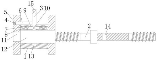
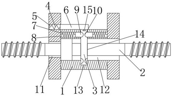
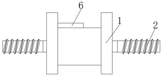
[0021] see Figure 1 to Figure 3 , the present invention includes a conductive bushing 1 and a terminal screw 2, and also includes a fixing column 3, the side of the conductive bushing 1 is provided with an opening 11 and an opening 12, and the terminal screw 2 passes through the opening 11 and the conductive bushing 1 Sliding connection, the surface of the conductive bushing 1 is provided with an opening 3 13 for the fixing column 3 to penetrate and slide, an...


PUM


Abstract

The invention discloses a combined binding post, which comprises a conductive bushing, a binding post screw rod and a fixed column, wherein the side surface of the conductive bushing is provided with an opening I and an opening II, the binding post screw rod is slidably connected with the conductive bushing through the opening I, an opening III for the fixed column to penetrate and slide is formed in the surface of the conductive bushing, a fourth opening for the fixing column to penetrate through and slide is formed in the surface of the binding post screw rod, and the binding post screw rod is made of martensitic stainless steel materials; and the combined binding post further comprises two clamping structures, and the fixed column is fixed under the action of the two clamping structures through vertical movement of the fixed column. The strength of the whole structure is guaranteed by using the high-strength binding post screw rod made of stainless steel, and the effect of guaranteeing the stability of the whole structure is achieved by using the fixed column and matching the fixed column with the clamping mechanisms.

Description

technical field [0001] The invention relates to the technical field of terminal, in particular to a combined terminal. Background technique [0002] At present, in the field of aviation airborne electronic equipment, the input or output terminals of a large number of airborne electronic equipment are in the form of binding posts. Therefore, it will be paralyzed and cannot work normally, so the requirements for the strength, service life and reliability of the binding post are becoming more and more stringent. [0003] At present, most of the existing combined terminals are made of copper alloy material as a whole. If the threads at both ends are easily worn out if they are frequently disassembled and assembled, they cannot effectively cooperate with the nuts. The nuts will loosen during the vibration of the airborne electronic equipment, so that the screws installed on the The lugs on the terminals cannot be effectively attached, which affects the input or output of the air...

Claims


Application Information

Patent Timeline
Patent Type & Authority Applications(China)
IPC IPC(8): H01R4/30H01R4/62H01R9/00
CPCH01R4/305H01R4/62H01R9/00
Inventor 李小东龙先飞张篙
Owner GUIYANG AVIATION MOTOR
Why Eureka
Try Eureka