Flexible sealing device
A technology of flexible sealing and sealing seat, which is applied in machine/engine, leakage prevention, mechanical equipment, etc., can solve the problems of wear, low pressure bearing capacity, large leakage, etc., and achieve low leakage rate, low cost of use, and sealing performance. high effect
- Summary
- Abstract
- Description
- Claims
- Application Information
AI Technical Summary
Problems solved by technology
Method used
Image


Examples
Embodiment 1
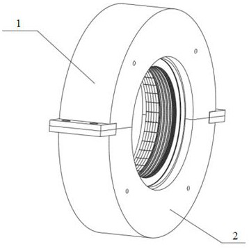
[0030] Embodiment 1: as Figure 1-11As shown, a flexible sealing device includes an upper seal seat 1, a lower seal seat 2, a grate seal 3, a front baffle 4, a fingertip seal 5, a partition 6, a brush wire 7, a rear baffle 8, The flexible support 9; the upper seal seat 1 and the lower seal seat 2 are provided with placement grooves I29, and the grate tooth seal 3 is fitted with a flexible support member 9 installed in the placement groove I29 of the lower seal seat 2. Multiple fingertips The sealing sheet 5 is clamped and installed in the middle of the front baffle 4 and the partition 6, the front baffle 4 fits the upper part of the grate seal 3 and the flexible support 9, the front baffle 4, the fingertip sealing sheet 5, and the partition 6 are all Installed in the placement groove Ⅰ29 of the lower seal seat 2, the brush filament 7 is fixedly installed in the rear baffle 8, one side of the rear baffle 8 fits the partition 6 and installed in the placement groove Ⅰ29 of the lo...
Embodiment 2
[0035] Embodiment 2: as Figure 1-11 As shown, a flexible sealing device includes an upper seal seat 1, a lower seal seat 2, a grate seal 3, a front baffle 4, a fingertip seal 5, a partition 6, a brush wire 7, a rear baffle 8, The flexible support 9; the upper seal seat 1 and the lower seal seat 2 are provided with placement grooves I29, and the grate tooth seal 3 is fitted with a flexible support member 9 installed in the placement groove I29 of the lower seal seat 2. Multiple fingertips The sealing sheet 5 is clamped and installed in the middle of the front baffle 4 and the partition 6, the front baffle 4 fits the upper part of the grate seal 3 and the flexible support 9, the front baffle 4, the fingertip sealing sheet 5, and the partition 6 are all Installed in the placement groove Ⅰ29 of the lower seal seat 2, the brush filament 7 is fixedly installed in the rear baffle 8, one side of the rear baffle 8 fits the partition 6 and installed in the placement groove Ⅰ29 of the l...
Embodiment 3
[0039] Embodiment 3: as Figure 1-11 As shown, a flexible sealing device includes an upper seal seat 1, a lower seal seat 2, a grate seal 3, a front baffle 4, a fingertip seal 5, a partition 6, a brush wire 7, a rear baffle 8, The flexible support 9; the upper seal seat 1 and the lower seal seat 2 are provided with placement grooves I29, and the grate tooth seal 3 is fitted with a flexible support member 9 installed in the placement groove I29 of the lower seal seat 2. Multiple fingertips The sealing sheet 5 is clamped and installed in the middle of the front baffle 4 and the partition 6, the front baffle 4 fits the upper part of the grate seal 3 and the flexible support 9, the front baffle 4, the fingertip sealing sheet 5, and the partition 6 are all Installed in the placement groove Ⅰ29 of the lower seal seat 2, the brush filament 7 is fixedly installed in the rear baffle 8, one side of the rear baffle 8 fits the partition 6 and installed in the placement groove Ⅰ29 of the l...
PUM
 Abstract
Description
Claims
Application Information
 - R&D
- Intellectual Property
- Life Sciences
- Materials
- Tech Scout
- Unparalleled Data Quality
- Higher Quality Content
- 60% Fewer Hallucinations
Browse by: Latest US Patents, China's latest patents, Technical Efficacy Thesaurus, Application Domain, Technology Topic, Popular Technical Reports.
© 2025 PatSnap. All rights reserved.Legal|Privacy policy|Modern Slavery Act Transparency Statement|Sitemap|About US| Contact US: help@patsnap.com