
Retaining wall drainage method and retaining wall drainage system

A technology of drainage system and retaining wall, applied in water conservancy projects, underwater structures, artificial islands, etc., can solve the problems of easily blocked drainage holes, collapse of retaining walls, and inability to discharge water accumulated in retaining walls.

Inactive Publication Date: 2021-04-13
广州市设计院集团有限公司
View PDF6 Cites 0 Cited by
  • Summary
  • Abstract
  • Description
  • Claims
  • Application Information

AI Technical Summary

Problems solved by technology

However, after a period of use, the drain hole is easily blocked, resulting in the accumulation of water on the side of the retaining wall cannot be discharged
When the accumulation of water increases, especially after the heavy rain, the retaining wall needs to bear the huge pressure from the side of the soil, and the retaining wall is prone to collapse

Method used


Image

  • Retaining wall drainage method and retaining wall drainage system
  • Retaining wall drainage method and retaining wall drainage system
  • Retaining wall drainage method and retaining wall drainage system

Examples


Embodiment Construction

[0038] In order to make the above objects, features and advantages of the present invention more comprehensible, specific implementations of the present invention will be described in detail below in conjunction with the accompanying drawings. In the following description, numerous specific details are set forth in order to provide a thorough understanding of the present invention. However, the present invention can be implemented in many other ways different from those described here, and those skilled in the art can make similar improvements without departing from the connotation of the present invention, so the present invention is not limited by the specific implementations disclosed below.

[0039] It should be noted that when an element is referred to as being “fixed” to another element, it can be directly on the other element or there can also be an intervening element. When an element is referred to as being "connected to" another element, it can be directly connected ...


PUM

PropertyMeasurementUnit
Diameteraaaaaaaaaa
Thicknessaaaaaaaaaa
Depthaaaaaaaaaa

Abstract

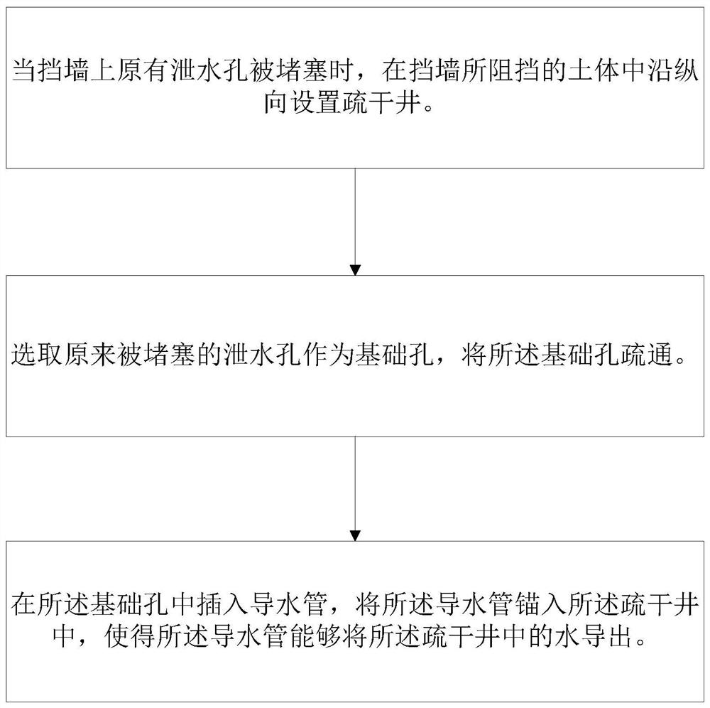
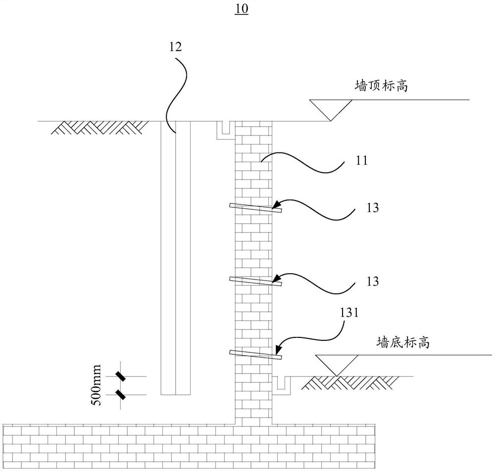
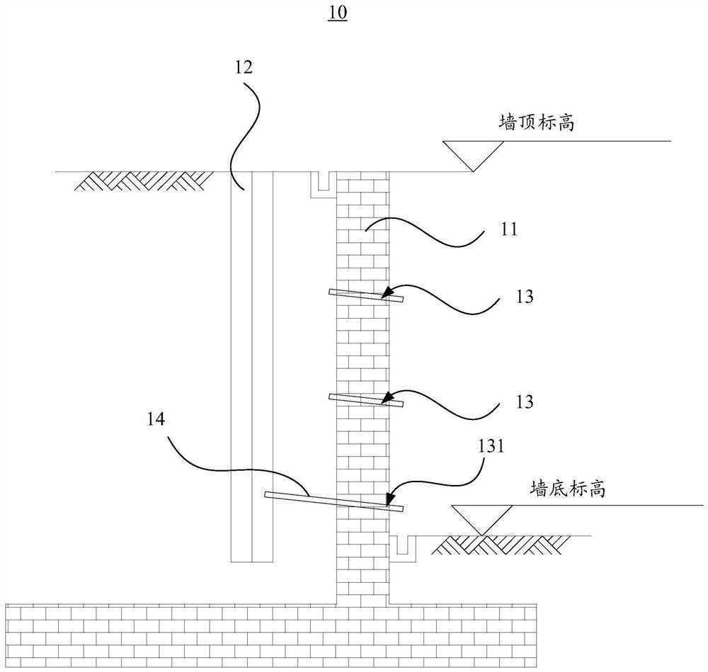
The invention relates to a retaining wall drainage method and a retaining wall drainage system. The retaining wall drainage method comprises the following steps that when an original drainage hole in a retaining wall is blocked, a drainage well is arranged in a soil body blocked by the retaining wall along the longitudinal direction; the originally blocked water drainage hole is selected as a foundation hole, a water guide pipe is inserted into the foundation hole, and the water guide pipe is anchored into the drainage well, so that the water guide pipe can guide out water in the drainage well; therefore, the purpose of draining is achieved, and water drainage capacity of the retaining wall is recovered. Moreover, in the process of recovering the water drainage capacity of the retaining wall, and the originally blocked water drainage hole is directly used as the foundation hole, so that the cost required for recovering the water drainage capacity of the retaining wall is effectively reduced, and meanwhile, the whole process is simpler and easier to implement. Moreover, by adopting the drainage well and the water guide pipe, the water drainage capacity of the retaining wall can be recovered for a long time, and the retaining wall is not easy to block.

Description

technical field [0001] The invention relates to the construction field of retaining wall drainage engineering, in particular to a retaining wall drainage method and a retaining wall drainage system. Background technique [0002] In construction fields such as roads or bridges, by setting a retaining wall on one side of the slope or filling, the soil is blocked on the side of the retaining wall, so as to achieve the purpose of shaping the soil and avoiding the loss of filling. In order to allow the accumulated water in the soil blocked by the retaining wall to be discharged smoothly, a weep hole will be provided in the retaining wall, and the weep hole will pass through both sides of the retaining wall to drain the accumulated water in the soil. Water drains. However, after a period of use, the drain hole is easily blocked, causing the accumulated water on one side of the retaining wall to be unable to be discharged. When the accumulated water increases, especially after he...

Claims


Application Information

Patent Timeline
IPC IPC(8): E02D3/10E02D29/02
CPCE02D3/10E02D29/02E02D2300/0007
Inventor 黄俊光林祖锴罗永健
Owner 广州市设计院集团有限公司
Learn More