Lifting welding support for automobile welding fixture with self-locking function
A technology of automobile welding fixture and welding bracket, which is applied in welding equipment, auxiliary welding equipment, welding/cutting auxiliary equipment, etc. Sex, the effect of reducing human and material resources
- Summary
- Abstract
- Description
- Claims
- Application Information
AI Technical Summary
Problems solved by technology
Method used
Image
Examples
Embodiment 1
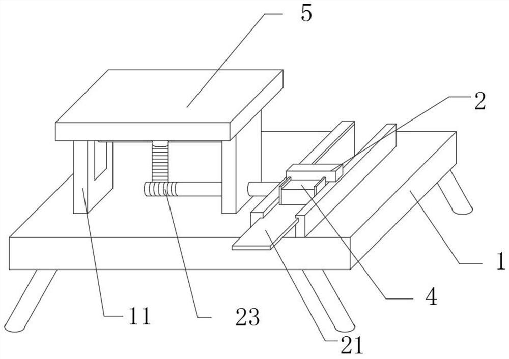
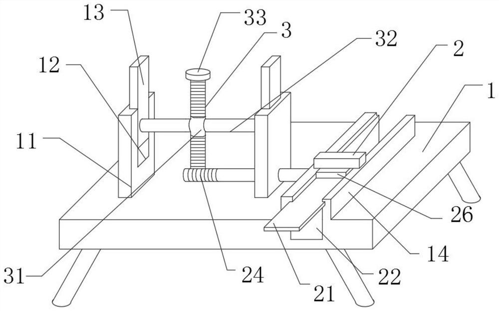
[0018] The invention provides a lifting welding bracket for automobile welding fixture with self-locking function, which is characterized in that it includes a bracket platform 1, a mounting block 14, a lifting mechanism, a propulsion mechanism, and a locking mechanism. Block 14, the installation block 14 and the support platform 1 are integrally structured, the support platform 1 and the installation block 14 are provided with a propulsion mechanism, the upper side of the propulsion mechanism is provided with a locking mechanism, the upper side of the support platform 1 is provided with a lifting mechanism, and the lifting mechanism is set on the left side of the propulsion mechanism;
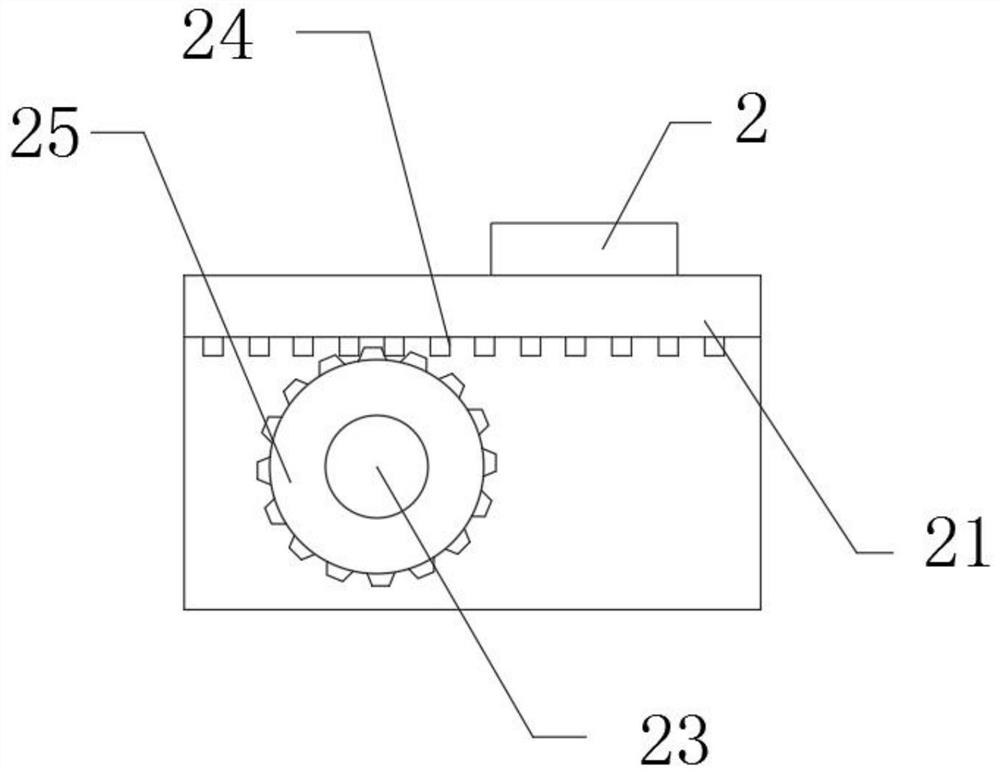
[0019] The lifting mechanism is composed of an adjusting bracket 11, a mounting block 14, a lifting slider 13, a connecting block 31, a connecting rod 32, a turbine 28, a screw 3, a bearing 33, a sliding plate 21, and the left and right ends of the bracket platform 1 top are respectively welded...
Embodiment 2
[0023] Before the present invention is used, it needs to be used in cooperation with the automobile welding fixture with self-locking function, and the automobile welding fixture with self-locking function is installed on the upper side of the installation platform 5. When the present invention is in use, at first the welding The workpiece is placed on the automobile welding jig with self-locking function, and the effect of self-locking can be realized through the action of the cylinder. The pushing block 2 is manually pushed longitudinally, and through the action of the gear 26 and the rack 25, the moving gear 26 drives the worm 24 accordingly. Rotate together, and then use the action of the turbine 28 and worm 24 to drive the connecting block 31 to move upwards together, and the connecting rod 32 connected to it realizes the effect of driving the lifting slider 13 to rise until the installation platform 5 rises to a suitable position, and the manual stop Push the pushing bloc...
PUM
 Abstract
Description
Claims
Application Information
 - R&D
- Intellectual Property
- Life Sciences
- Materials
- Tech Scout
- Unparalleled Data Quality
- Higher Quality Content
- 60% Fewer Hallucinations
Browse by: Latest US Patents, China's latest patents, Technical Efficacy Thesaurus, Application Domain, Technology Topic, Popular Technical Reports.
© 2025 PatSnap. All rights reserved.Legal|Privacy policy|Modern Slavery Act Transparency Statement|Sitemap|About US| Contact US: help@patsnap.com


