Internet-of-Things irrigation device

An irrigation device, the technology of the Internet of Things, which is applied to spray devices, fertilization devices, and devices for catching or killing insects, etc. The effect of Internet of Things remote control box automatic irrigation

Inactive Publication Date: 2021-04-13
南京迪梵安家具有限公司
View PDF0 Cites 0 Cited by
  • Summary
  • Abstract
  • Description
  • Claims
  • Application Information

AI Technical Summary

Problems solved by technology

[0004] Aiming at the deficiencies of the prior art, the present invention provides an irrigation device for the Internet of Things, which solves the problems of not being able to automatically feed when the irrigation liquid is used up, not being able to fertilize, and uneven distribution of medicine and fertilizer

Method used


Image

  • Internet-of-Things irrigation device
  • Internet-of-Things irrigation device
  • Internet-of-Things irrigation device

Examples


Embodiment 1

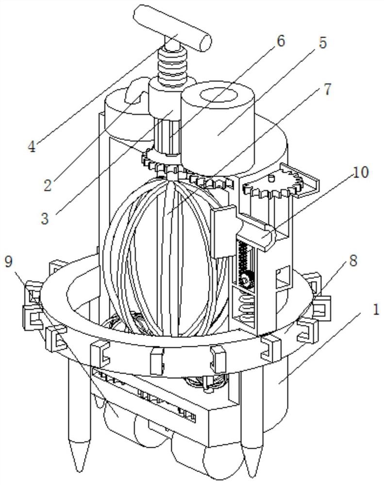
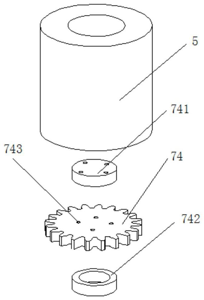
[0031] An IoT irrigation device, such as Figure 1-Figure 4 As shown, it includes a box body 1, the inside of the box body 1 is connected with a water pipe 2, the top of the box body 1 is welded with a spray seat 3, and the top of the spray seat 3 is rotatably connected with a nozzle 4, and the box body 1 is located on the right side of the spray seat 3 The medicine box 5 is connected by bolts, and the top of the inner wall of the box body 1 is connected with a motor 6 by bolts. There are traveling wheels 9, and a water inlet 10 is provided on the surface of the box body 1 above the fixing device 8.

[0032] In this embodiment, the stirring mechanism 7 includes a rotating rod 71, and the top of the rotating rod 71 is clamped and fixed with the output shaft of the motor 6. The surface of the rotating rod 71 is respectively welded with a driving gear 72 and a stirring fan 73, and the driving gear 72 is located at Above the stirring fan 73, the surface of the driving gear 72 is ...

Embodiment 2

[0041] Such as Figure 4-Figure 7 As shown, on the basis of Embodiment 1, in this embodiment, the automatic replenishment device 78 includes a return spring 781, the bottom end of the return spring 781 is welded and fixed to the inner wall of the side seat 771, and the top end of the return spring 781 is welded with a pressure plate 782 A tooth plate 783 is welded on the top of the pressing plate 782, and a slide plate 784 is welded on the left side of the tooth plate 783.

[0042] By setting the return spring 781 to achieve the effect that the slide plate 784 is always at the lowest point after receiving the continuous downward force of the tooth plate 783, and further achieve the effect that the slide plate 784 is always at the lowest point, which facilitates the effect of water flowing in from the water inlet 10. At the same time, by setting The return spring 781, through the influence of its own elastic force, reaches the effect that the tooth plate 783 is reset by the spr...


PUM


Abstract

The invention relates to the technical field of Internet-of-Things irrigation, and discloses an Internet-of-Things irrigation device which comprises a box body. The top of a spray seat is rotatably connected with a spray head, the box body is located at the right side of the spray seat and is connected with a pesticide box through a bolt, the top of the inner wall of the box body is connected with a motor through a bolt, and an output shaft of the motor is provided with a stirring mechanism. A fixing device is arranged on the surface of the box body, walking wheels are rotatably connected to the bottom of the box body, and a water inlet is formed in the position, located above the fixing device, of the surface of the box body. According to the Internet-of-Things irrigation device, an Internet-of-Things module is used for controlling the stirring mechanism and the fixing device to operate, the effect of automatically supplying pesticide fertilizer and irrigation water into the box body is achieved, meanwhile, the effect of stirring and mixing the pesticide fertilizer and the irrigation water while automatic supplying is achieved, and the problem that the health states of crops are inconsistent due to uneven mixing of the pesticide fertilizer is avoided; and the effect of integrally fixing and installing the box body is achieved through the fixing device.

Description

technical field [0001] The invention relates to the technical field of irrigation of the Internet of Things, in particular to an irrigation device of the Internet of Things. Background technique [0002] Irrigation is a technical measure to supplement the water needed by crops. In order to ensure the normal growth of crops and obtain high and stable yields, crops must be supplied with sufficient water. Under natural conditions, often due to insufficient precipitation or uneven distribution, it cannot meet the needs of crops for moisture. Requirements, therefore, must be artificially irrigated to make up for the lack of natural rainfall, and the existing irrigation methods are artificially irrigated by many people. If it can be combined with the Internet of Things, remote control irrigation can be performed, which greatly liberates the labor force . [0003] Most existing irrigation devices cannot remotely control automatic irrigation, and need to be manually controlled to s...

Claims


Application Information

Patent Timeline
IPC IPC(8): A01M7/00A01C23/04B05B15/25
CPCA01C23/042A01M7/0025A01M7/0089B05B15/25
Inventor 不公告发明人
Owner 南京迪梵安家具有限公司
Why Eureka
Try Eureka