Fish tank filter
A filter and fish tank technology, applied in fish farming, application, animal husbandry, etc., can solve the problems of affecting water circulation flow, unsatisfactory sedimentation effect, poor effect, etc.
- Summary
- Abstract
- Description
- Claims
- Application Information
AI Technical Summary
Problems solved by technology
Method used
Image


Examples
Embodiment 1
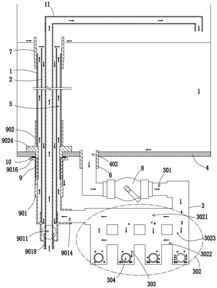
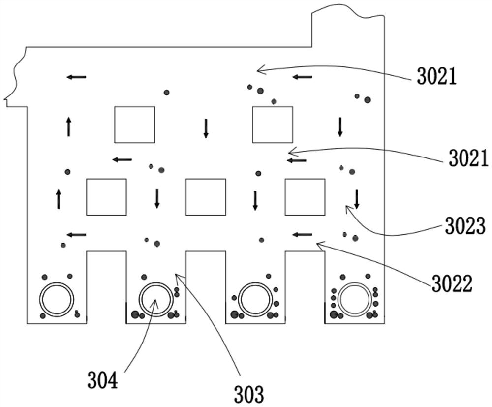
[0033] Please refer to Figure 1-Figure 3 . figure 1 It is a sectional view of the overall structure of the fish tank filter and the fish tank 4 shown in the embodiment of the present invention; figure 2 It is a sectional view of the overall structure of another embodiment of the fish tank filter and the fish tank 4 shown in the embodiment of the present invention; image 3 It is another structural schematic diagram of the precipitation zone 302 according to the embodiment of the present invention.
[0034] This embodiment provides a fish tank filter based on figure 1 and figure 2 As shown, it includes a water blocking pipe 1, an overflow drainage pipe 2 and a sedimentation pipe 3. The water blocking pipe 1 is sleeved on the outside of the overflow drainage pipe 2, and the outer diameter of the overflow drainage pipe 2 is smaller than the inner diameter of the water blocking pipe 1. The overflow drainage pipe 2 The top is communicated with the top of the water retaining ...
Embodiment 2
[0053] Please refer to figure 1 , figure 2 , Figure 4 , Figure 5 and Image 6 . figure 1 It is a sectional view of the overall structure of the fish tank filter and the fish tank 4 shown in the embodiment of the present invention; figure 2 It is a sectional view of the overall structure of another embodiment of the fish tank filter and the fish tank 4 shown in the embodiment of the present invention; Figure 4 is a partial view of Embodiment A of the present invention; Figure 5 It is a schematic diagram of the connection structure of the connector 901, the fastener 902 and the bottom of the fish tank 4 according to the embodiment of the present invention; Image 6 It is a schematic diagram of another connection structure of the connector 901, the fastener 902 and the bottom of the fish tank 4 according to the embodiment of the present invention.
[0054] This embodiment is proposed based on the technical solution of Embodiment 1: based on figure 1 , figure 2 and...
Embodiment 3
[0069] Please refer to figure 1 Figure 4 . figure 1 It is a sectional view of the overall structure of the fish tank filter and the fish tank 4 shown in the embodiment of the present invention; Figure 4 It is a partial view of Embodiment A of the present invention.
[0070] This embodiment proposes based on the technical solution of Embodiment 2: it also includes a water supply pipe 11, the water supply pipe 11 is sleeved on the inner side of the overflow drain pipe 2, the outer diameter of the water supply pipe 11 is smaller than the inner diameter of the overflow drain pipe 2, and the water supply pipe 11 is connected to the overflow drain pipe 2. The connector 901 is connected, one end of the water supply pipe 11 is communicated with the water source, and the other end of the water supply pipe 11 is used to inject water into the fish tank 4 .
[0071] In this embodiment, based on figure 1 , figure 2 and Figure 4 As shown, the connecting member 901 is provided with...
PUM
 Abstract
Description
Claims
Application Information
 - Generate Ideas
- Intellectual Property
- Life Sciences
- Materials
- Tech Scout
- Unparalleled Data Quality
- Higher Quality Content
- 60% Fewer Hallucinations
Browse by: Latest US Patents, China's latest patents, Technical Efficacy Thesaurus, Application Domain, Technology Topic, Popular Technical Reports.
© 2025 PatSnap. All rights reserved.Legal|Privacy policy|Modern Slavery Act Transparency Statement|Sitemap|About US| Contact US: help@patsnap.com