Circuit for direct-current synchronous boosting

A DC synchronization and circuit technology, which is applied in the direction of DC power input conversion to DC power output, electrical components, and adjustment of electrical variables, can solve the problems of lack of flexibility and poor consistency of current-limiting protection points, and achieve short-circuit monitoring and protection. , improve the effect of consistency

Pending Publication Date: 2021-04-09
SHANGHAI SHININGIC ELECTRONICS TECH CO LTD
View PDF0 Cites 0 Cited by
  • Summary
  • Abstract
  • Description
  • Claims
  • Application Information

AI Technical Summary

Problems solved by technology

[0008] However, in the prior art, the output overcurrent protection is realized by comparing the clamping of the output signal COMP of the error operational amplifier with the conduction voltage drop generated by the current on the power NMOS, so the overcurrent protection point is controlled by the power NMOS transistor Influenced by the on-resistance and temperature characteristics, the consistency is poor, and the fixed current-limiting protection point lacks flexibility, which has become one of the problems to be solved urgently by those skilled in the art

Method used


Image

  • Circuit for direct-current synchronous boosting
  • Circuit for direct-current synchronous boosting
  • Circuit for direct-current synchronous boosting

Examples


Embodiment Construction

[0068] Attached below Figure 3-5 , the specific embodiment of the present invention will be further described in detail.

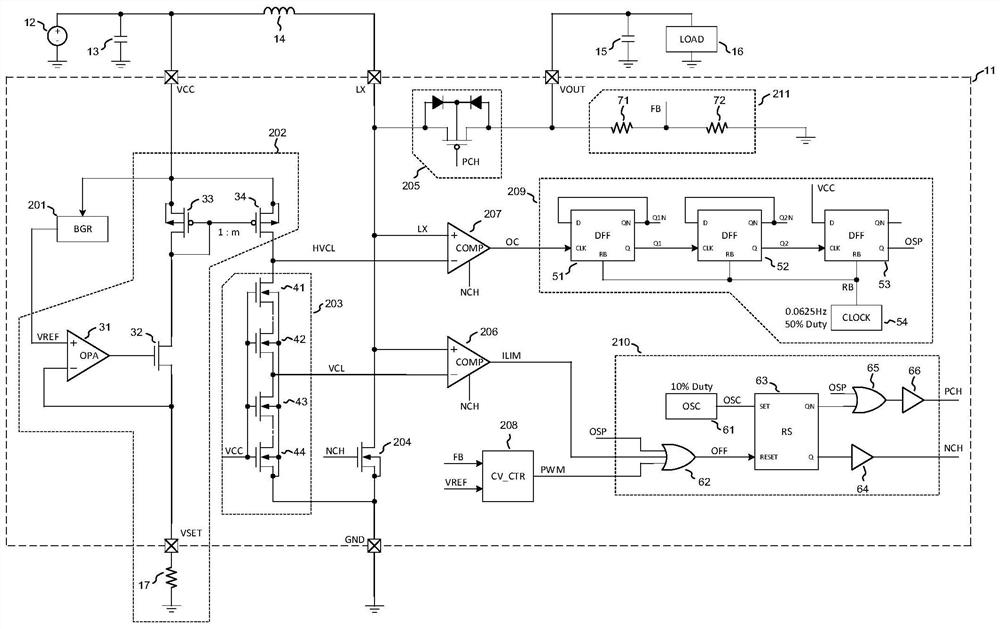
[0069] see image 3 , image 3 Shown is a schematic structural diagram of a DC synchronous step-up circuit in an embodiment of the present invention. Such as image 3 As shown, the DC synchronous boost circuit of the present invention includes a boost control chip 11 , an input power source 12 , an input capacitor 13 , an energy storage inductor 14 , an output capacitor 15 , a load 16 and an external programming resistor 17 .

[0070] The boost control chip 11 includes an overcurrent protection module 207, a current limiting protection module 206, a power supply port VCC, a port LX, an output port output terminal VOUT, a current limiting setting terminal VSET, and a ground terminal GND; the port LX terminal is connected to To one end of the energy storage inductance, the other end of the energy storage inductance 14 is connected to the power port VCC ...


PUM


Abstract

A circuit for direct-current synchronous boosting comprises a boosting control chip, an input power supply, an input capacitor, an energy storage inductor, an output capacitor, a load and an external programming resistor. The boosting control chip comprises an over-current protection module and a current-limiting protection module. A port LX end is connected to one end of the energy storage inductor, and the other end of the energy storage inductor is connected to a power supply port VCC end of the boosting control chip, an anode of the input capacitor and the anode of the input power supply; the output port output end VOUT of the boosting control chip is connected to the anode of the output capacitor, and a load is connected in series between the output port output end VOUT and a grounding end GND; the external programming resistor is connected in series between a current-limiting setting end VSET and the grounding end GND of the boosting control chip; the cathode of the input power supply, the cathode of the input capacitor and the cathode of the output capacitor are all connected to the ground end GND; and a current-limiting protection module enables an over-current protection module to limit the current of the load to a preset threshold value after the load is over-current, and the preset threshold value is related to the resistance value of the external programming resistor.

Description

technical field [0001] The invention belongs to the technical field of circuits, and relates to a circuit for DC synchronous voltage boosting. Background technique [0002] In recent years, DC synchronous boost has been widely developed and applied as a power management product, realizing high-efficiency DC-to-DC power conversion and being used in various environments and occasions. [0003] see figure 1 , figure 1 Shown is a schematic diagram of a DC synchronous boost protection circuit in the prior art. Such as figure 1 As shown, the LX end of the control chip 101 is connected to the inductor 14, and the other end of the inductor 14 is connected to the power supply terminal VCC of the chip 101, the positive pole of the input capacitor 13 and the positive pole of the input power supply 12; the output terminal VOUT of the chip 101 is connected to To the positive pole of the output capacitor 15, a load 16 is connected in series between the output terminal VOUT and the gro...

Claims


Application Information

Patent Timeline
Patent Type & Authority Applications(China)
IPC IPC(8): H02M3/156H02M1/32
CPCH02M3/156H02M1/32
Inventor 班福奎孙竞赛
Owner SHANGHAI SHININGIC ELECTRONICS TECH CO LTD
Why Eureka
Try Eureka