


Quick Research
Generate reliable direction feasibility study reports for your R&D in just a few steps.

Technical Q&A
Discover and master advanced knowledge NOW. Basics, ideas, possibilities, all at once.

Find Solutions
As an expert in R&D theories, this can generate solutions to your technical problems instantly.

Evaluate Feasibility
Analyze your overall solution with one click, know your potential R&D risks in advance.

Monitor Landscape
Get weekly tech updates, stay abreast of the latest tech innovations and key insights.
An advanced laser drilling machine mounted on a tbm and its working method
A laser and drilling rig technology, applied in the field of advanced exploration, can solve the problems that the effect cannot meet the ideal expectation, and achieve the effect of increasing the rock breaking efficiency, high hole quality and low reliability
- Summary
- Abstract
- Description
- Claims
- Application Information
AI Technical Summary
Problems solved by technology
Method used
Image


Examples
Embodiment 1
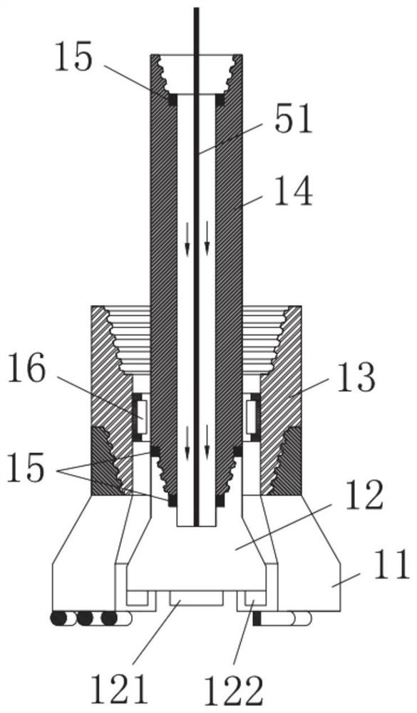
[0067] Such as Figure 1-Figure 7 As shown, Embodiment 1 of the present disclosure provides an advanced laser drilling machine mounted on a TBM, including a laser drill bit 1, a laser drill rod 2, a drilling machine main body mechanism 3, a laser generating mechanism 5, a laser optical fiber 51, a multifunctional joint 37 and Slag removal device.
[0068] The laser generating mechanism 5 provides a laser source, and the laser light is delivered to the laser drill bit 12 through the laser fiber 51 through the laser drill rod 2 for release. The laser drill rod 2 continues to follow up to realize continuous and fast drilling. The water pump 6 provides a certain pressure fluid through the fluid pipeline 61 to flush out the cuttings in the drill hole and cool the laser drill bit.
[0069] The laser drill bit 1 includes a laser emitting terminal 121, a slag discharge fluid port 122, a mechanical hole cleaning drill bit 11 and a drilling tool connection part. The laser emitting term...
Embodiment 2
[0091] Embodiment 2 of the present disclosure provides a full-face hard rock tunnel boring machine, including the laser drilling machine provided in Embodiment 1. Specifically for the current TBM structure and construction characteristics, the laser drilling machine adopts the following loading scheme and usage method:
[0092] The main mechanism of the drilling rig is installed on the TBM main beam 72 on the rear side of the TBM cutter head drive 73, where there is a certain amount of available space, and it is the closest applicable area to the face 8; the main mechanism of the drilling rig 3 is installed here , The number of external auxiliary drill pipes required for drilling in the advance drilling process is the least, which is conducive to the rapid preparation of drilling and the recovery of drill pipes.
[0093] Open holes on the TBM main beam 72 between the face and the main body of the drilling rig, and correspondingly open holes on the TBM cutter head 71 as the work...
Embodiment 3
[0098] Embodiment 3 of the present disclosure provides a working method of the laser drilling machine described in Embodiment 1, using the full-section hard rock tunnel boring machine provided in Embodiment 1, including the following steps:
[0099] The TBM rotates the cutterhead 71 to a designated position, so that the opening on the cutterhead matches the work of the laser drill 2;
[0100] Install the laser drill rod 2 and the laser drill bit 1 between the face 8 and the main body mechanism 3 of the drilling rig;
[0101] The generated slag discharge fluid is ejected from the slag discharge fluid port 122, and the generated laser is released from the laser emission terminal 121
[0102] The laser drill rod 2 is continuously advanced to perform laser drilling, and at the same time, the outer drill rod drives the mechanical hole cleaning drill bit 11 to remove the molten material on the hole wall, exposing the original rock and cracks;
[0103] When a drilling construction s...
PUM
 Abstract
Description
Claims
Application Information
 - R&D Engineer
- R&D Manager
- IP Professional
- Industry Leading Data Capabilities
- Powerful AI technology
- Patent DNA Extraction
Browse by: Latest US Patents, China's latest patents, Technical Efficacy Thesaurus, Application Domain, Technology Topic, Popular Technical Reports.
© 2024 PatSnap. All rights reserved.Legal|Privacy policy|Modern Slavery Act Transparency Statement|Sitemap|About US| Contact US: help@patsnap.com