
Cooling liquid recovery process for six-axis grinding machine

A cooling fluid and grinding machine technology, applied in manufacturing tools, metal processing equipment, grinding/polishing equipment, etc., can solve the problems of inability to discharge iron filings and grinding stone particles, increase the difficulty of filtration, and be impossible to achieve, so as to improve the use of water circulation. effect, increase the difficulty of filtering, and improve the effect of utilization

Inactive Publication Date: 2021-04-09
浙江威步机器人股份有限公司
View PDF1 Cites 3 Cited by
  • Summary
  • Abstract
  • Description
  • Claims
  • Application Information

AI Technical Summary

Problems solved by technology

[0006] The purpose of the present invention is to address the deficiencies of the prior art. By setting the output of iron filings to cooperate with the collection of waste water, the impurities adhering to the water can be collected in two parts, and then the impurities can be completely removed, even if the grinding work is completed. Finally, there is no need to clean the workpiece grinding station every time. In addition, the impurities collected on both sides are screened, which is beneficial to the recycling of iron filings and improves the utilization rate of raw materials. At the same time, water, iron filings and grinding stone particles are While sorting, output in time to avoid re-mixing with subsequent water and increase the difficulty of filtration, thus solving the problem that the iron filings and millstone particles cannot be discharged in time, resulting in low water flow, and the amount of water output that cannot be achieved will be nearly equal The technical problem of timely circulation and backflow of water

Method used


Image

  • Cooling liquid recovery process for six-axis grinding machine
  • Cooling liquid recovery process for six-axis grinding machine
  • Cooling liquid recovery process for six-axis grinding machine

Examples


Embodiment 1

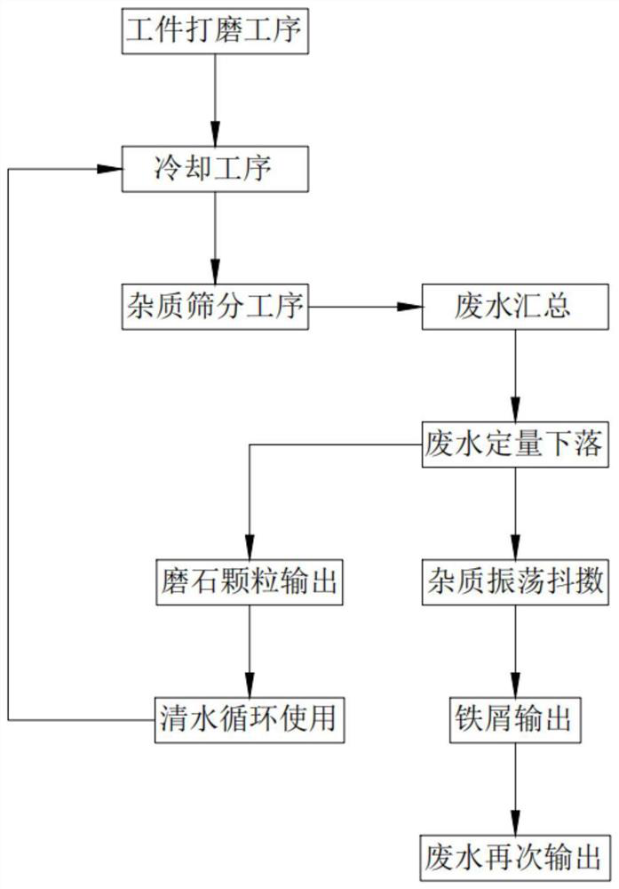
[0058] Such as figure 1 As shown, a coolant recovery process for a six-axis grinder includes a workpiece grinding process, a cooling process, and an impurity screening process, and the impurity screening process includes:

[0059] Step 1, the wastewater is collected, the grinding mechanism 2 drives the impurity removal mechanism 5 to work through the first transmission mechanism 8, when any support shaft 52 moves towards the support plate 42, the other support shaft 52 moves away from the support plate 42, and then the support plate Impurities on the 42 are blown into the installation chamber 51 moving away from the support plate 42 along the airflow direction, that is, the impurities entering the installation chamber 51 are also subjected to the blowing force while being attracted, and the impurities are accelerated to enter the installation chamber 51 The speed, then the impurities entering the installation chamber 51 enter the discharge chute 503 along the discharge part 50...

Embodiment 2

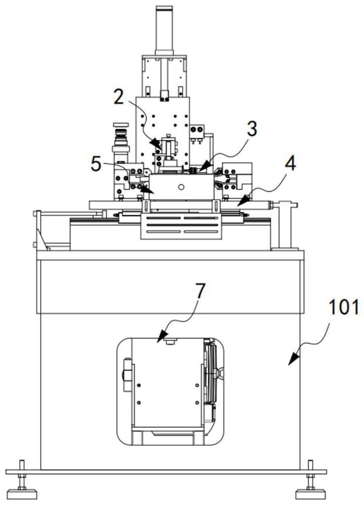
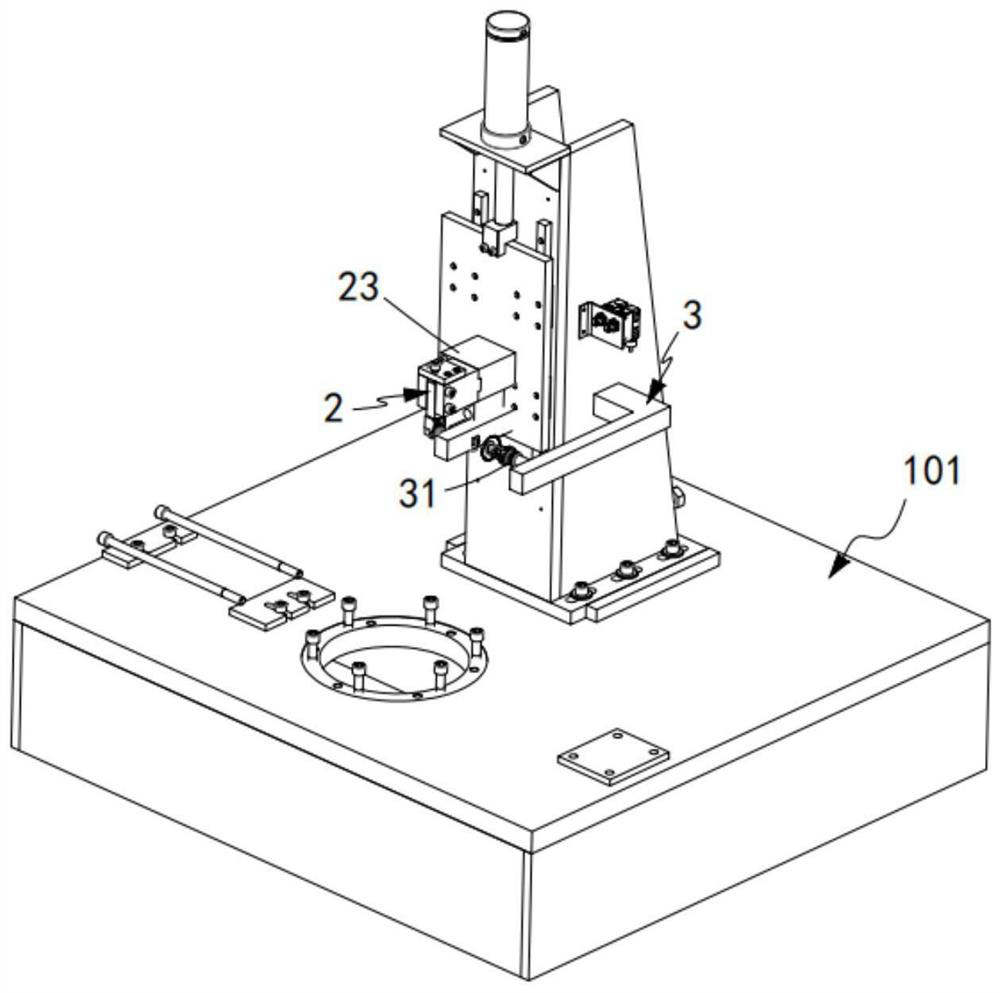
[0077] Such as figure 2 As shown, a water cooling machine for a round table surface grinder includes a grinder 101, a grinding mechanism 2 installed on the grinder 101, a cooling mechanism 3 arranged on one side of the grinding mechanism 2, and a cooling mechanism 3 arranged below the grinding mechanism 2. And the carrying mechanism 4 installed on the grinding machine 101, two sets of impurity removal mechanisms 5 arranged symmetrically on both sides of the carrying mechanism 4 and used to collect impurities on the carrying mechanism 4, arranged on the An iron filings filter mechanism 6 arranged under the impurity removal mechanism 5 and communicated with the impurity removal mechanism 5 , and a grindstone particle filter mechanism 7 arranged under the iron filings filter mechanism 6 and communicated with the cooling mechanism 3 at the other end;

[0078]The impurity removal mechanism 5 works synchronously with the grinding mechanism 2 through the first transmission mechanism...


PUM


Abstract

The invention relates to a cooling liquid recovery process for a six-axis grinding machine. The process comprises a workpiece grinding process, a cooling process and an impurity screening process, wherein the impurity screening process comprises the following steps: 1, gathering wastewater; 2, quantitatively dropping the wastewater; 3, shaking off impurities by oscillation; 4, outputting scrap iron; 5, outputting clean water; 6, outputting millstone particles; and 7, recycling clear water. The technical problems that scrap iron and millstone particles cannot be discharged in time, consequently, the water flow is low, output of much water cannot be achieved, and nearly equal amount of water circulates and flows back in time are solved.

Description

technical field [0001] The invention relates to the technical field of six-axis grinding machines, in particular to a cooling liquid recovery process for six-axis grinding machines. Background technique [0002] The grinding process of the existing version rollers generally uses the positioning mechanism of the six-axis grinder to position the version rollers of different widths. The copper layer on the surface of the roller is polished smooth to obtain a smooth copper plated roller. [0003] When the six-axis grinder grinds the outer surface of the plate roller, the plate roller rotates relative to the supporting mechanism, and there should be no rotation or looseness relative to the bed. When the plate roller rotates, the top head of the supporting mechanism and the plate There is a huge sliding friction between the end faces of the rollers, which makes the tip cone wear quickly, resulting in a short life of the tip. The grinding machine needs to use coolant during the g...

Claims


Application Information

Patent Timeline
Patent Type & Authority Applications(China)
IPC IPC(8): B24B55/02B24B55/03
CPCB24B55/02B24B55/03
Inventor 胡文明
Owner 浙江威步机器人股份有限公司
Learn More