
Axial stretching machining equipment for thin-wall slender shaft parts and method

A technology of axial stretching and processing equipment, applied in the field of mechanical processing, can solve problems such as affecting processing accuracy and roughness, uneven cutting depth, bending deformation of parts, etc., to improve the quality of processed products, improve residual stress distribution, The effect of reducing processing distortion

Active Publication Date: 2021-04-09
XI AN JIAOTONG UNIV +1
View PDF8 Cites 2 Cited by
  • Summary
  • Abstract
  • Description
  • Claims
  • Application Information

AI Technical Summary

Problems solved by technology

[0002] With the development of aero-engine materials and manufacturing technology in the direction of composite, lightweight, integrated, high-efficiency and low-cost, the weight of engine components is getting lighter and lighter. Since most of the parts are thin-walled and slender shaft parts, The parts are slender and have poor rigidity. The radial cutting force during processing can easily cause the parts to bend and deform and cause vibration, which affects the machining accuracy and roughness. On the other hand, due to the thin wall thickness and poor rigidity, the clamping force and radial cutting Under the action of force, it is easy to deform, resulting in uneven cutting depth and the phenomenon of letting the knife

Method used


Image

  • Axial stretching machining equipment for thin-wall slender shaft parts and method
  • Axial stretching machining equipment for thin-wall slender shaft parts and method
  • Axial stretching machining equipment for thin-wall slender shaft parts and method

Examples


Embodiment Construction

[0024] The technical solution of the present invention will be further described below in conjunction with the drawings and embodiments, but the scope of protection is not limited to the description.

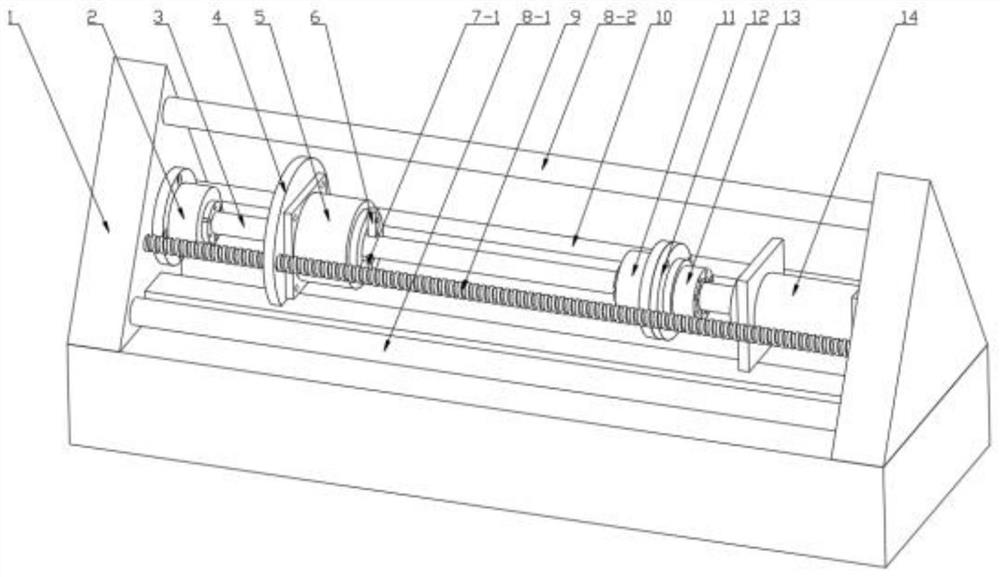
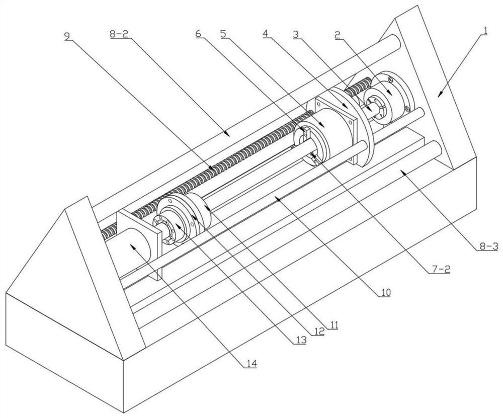
[0025] Such as figure 1 , figure 2 As shown, a thin-walled slender shaft parts axial stretching processing equipment includes a base 1, and a first column 8-1, a second column 8-2 and a third column are connected between the left and right support surfaces on the upper part of the base 1. Column 8-3, three columns strengthen the rigidity of the equipment; the left hydraulic chuck 2 is fixed by bolts on the inner side of the left support surface, the left hydraulic chuck 2 and the right hydraulic chuck 11 clamp thin-walled slender shaft parts 3, and the right hydraulic chuck The head 11 is installed on the left side of the sensor connector 12, and the tension and pressure sensor 13 is installed on the right side of the sensor connector 12. The tension and pressure sensor 13 is ...


PUM


Abstract

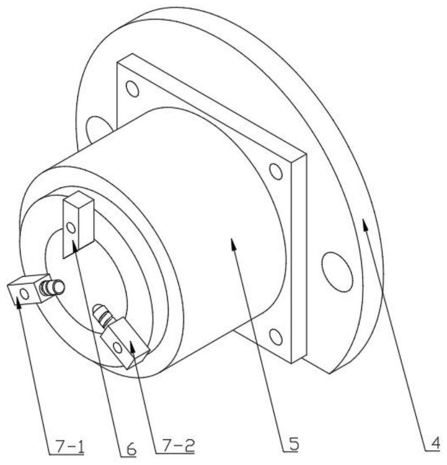
The invention discloses axial stretching machining equipment for thin-wall slender shaft parts and a method. The axial stretching machining equipment comprises a base, a left hydraulic chuck is fixed to the inner side of the left supporting face of the base, the left hydraulic chuck and a right hydraulic chuck clamp the thin-wall slender shaft parts, the right hydraulic chuck is installed on a sensor connecting piece, the sensor connecting piece is connected with a hydraulic cylinder through an installation tension and compression sensor, and the hydraulic cylinder is fixed on the right supporting surface of the base; and a ball screw and a driven shaft are connected between the left supporting face and the right supporting face of the base, a motor fixing base is connected to the ball screw and the driven shaft, a disc type motor is installed on the motor fixing base, turning tools, first supporting idler wheels and second supporting idler wheels which are in contact with the thin-wall slender shaft parts are evenly distributed and installed on a rotating disc of the disc type motor, head balls of the two supporting idler wheels can rotate freely, and radial feeding is achieved through threads. The method adopts a route of pre-stretching, rough machining, pre-stretching, semi-finish machining, pre-stretching and finish machining. The cutting performance is improved, and machining deformation is effectively prevented.

Description

technical field [0001] The invention relates to the technical field of mechanical processing, in particular to an axial stretching processing device and method for thin-walled slender shaft parts. Background technique [0002] With the development of aero-engine materials and manufacturing technology in the direction of composite, lightweight, integrated, high-efficiency and low-cost, the weight of engine components is getting lighter and lighter. Since most of the parts are thin-walled and slender shaft parts, The parts are slender and have poor rigidity. The radial cutting force during processing can easily cause the parts to bend and deform and cause vibration, which affects the machining accuracy and roughness. On the other hand, due to the thin wall thickness and poor rigidity, the clamping force and radial cutting Under the action of force, it is easy to deform, resulting in uneven depth of knife penetration and the phenomenon of knife letting. How to better improve t...

Claims


Application Information

Patent Timeline
IPC IPC(8): B23P15/00B21D22/20
CPCB23P15/00B21D22/20
Inventor 张琦王聚存徐宏图罗伟李均陈超群
Owner XI AN JIAOTONG UNIV
Learn More