Building construction steel bar cut-off machine with multi-angle position cutting function

A steel bar cutting machine and construction technology, which is applied in the field of steel bar cutting machine, can solve the problems such as the manual hand-held steel bar grinding angle is not smooth enough, wastes time to use manual hand-held steel bar grinding angle, and cannot meet the special requirements of the steel bar angle, etc., to achieve convenience Adjust the cutting position, save manual labor, and prevent cutting deviation

Inactive Publication Date: 2021-04-09
缪凤通
View PDF0 Cites 0 Cited by
  • Summary
  • Abstract
  • Description
  • Claims
  • Application Information

AI Technical Summary

Problems solved by technology

It is one of the essential equipment for steel bar processing. It is mainly used for cutting steel bars at fixed lengths in building construction. The existing steel bar cutting machines can only cut steel bar materials at fixed points, and cannot adjust the angle of cutting steel bar materials, which cannot meet some requirements. There are special requirements for the angle of steel bars in construction, which wastes time and is inefficient to use manual hand-held steel bar grinding angles, which is inefficient. Manual hand-held steel bar grinding angles are not smooth enough, and the butt joint will lead to failure to fit, thereby reducing work efficiency.

Method used


Image

  • Building construction steel bar cut-off machine with multi-angle position cutting function
  • Building construction steel bar cut-off machine with multi-angle position cutting function
  • Building construction steel bar cut-off machine with multi-angle position cutting function

Examples


Embodiment 1

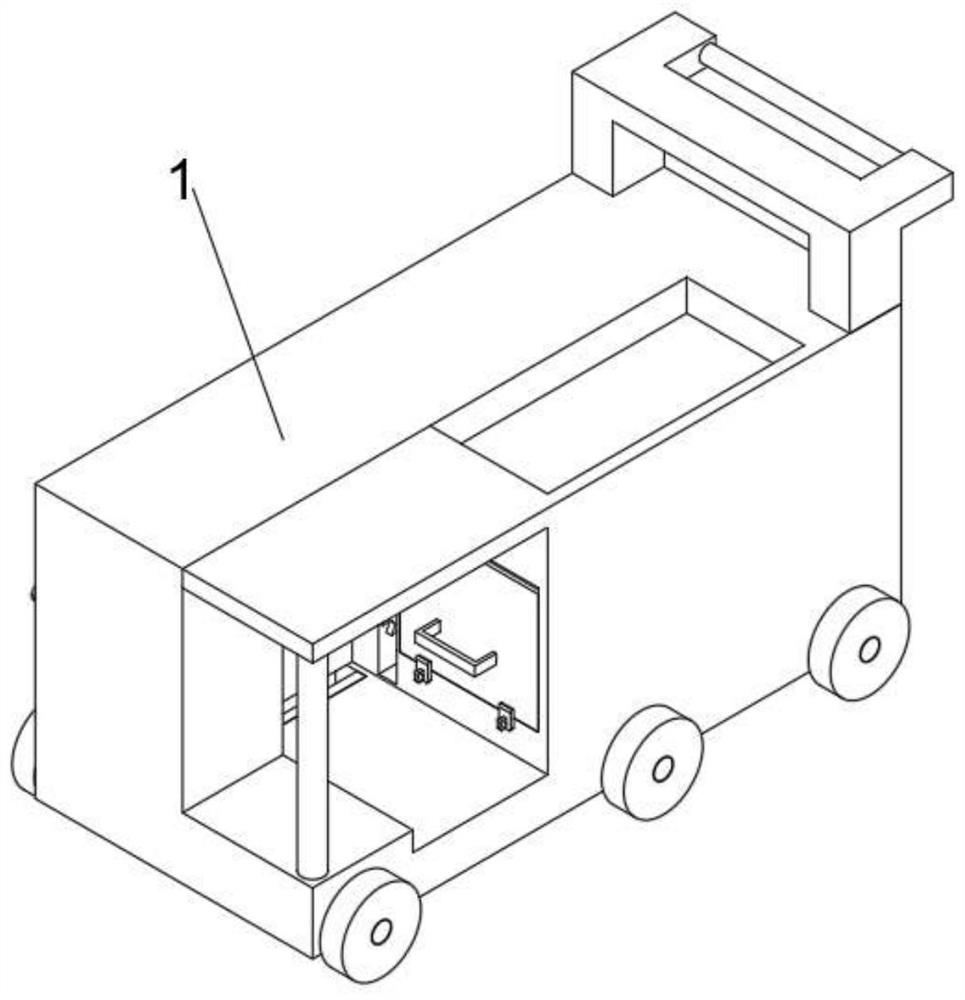
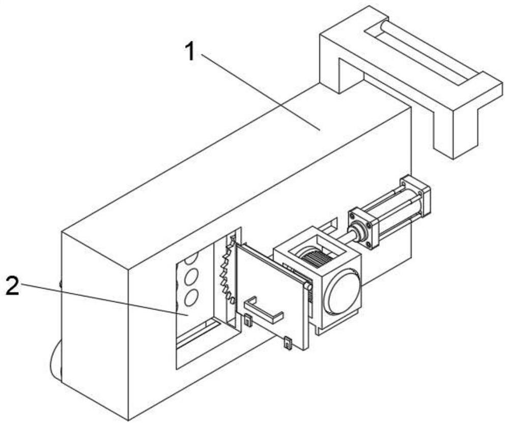
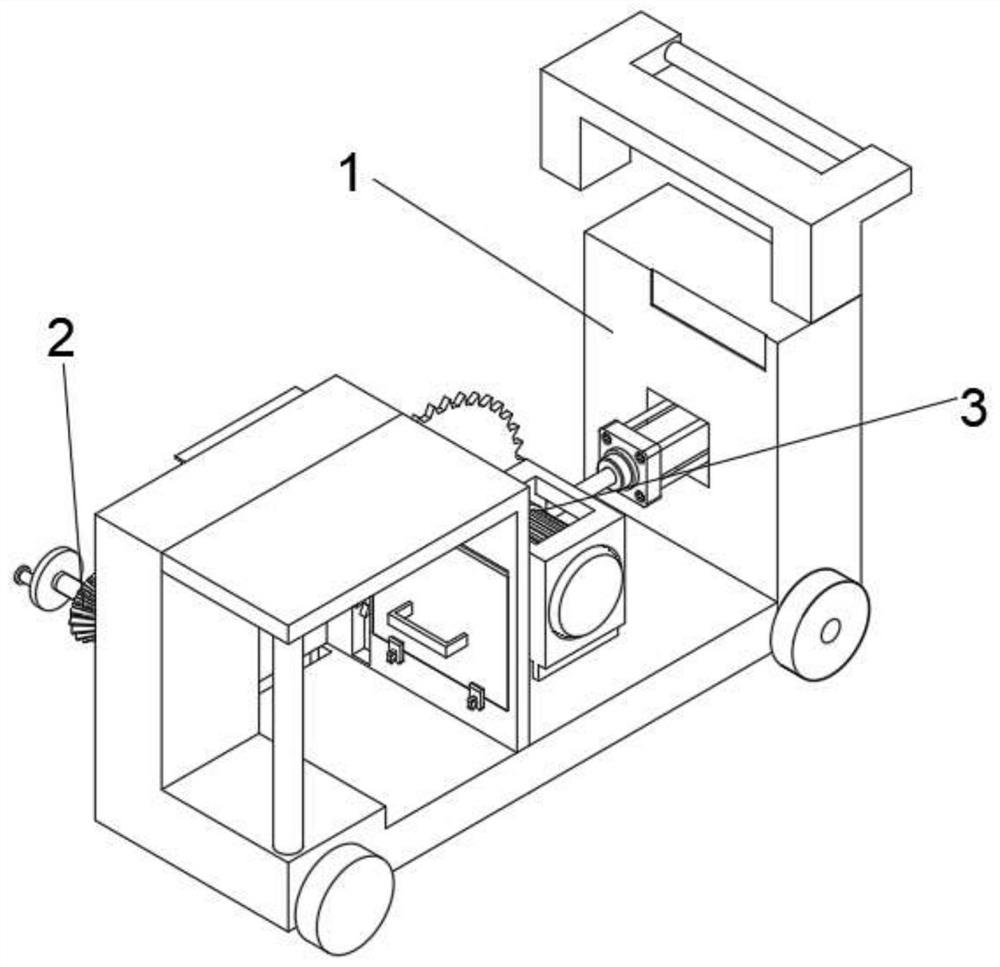
[0049] see Figure 1-Figure 10 As shown, there is provided a kind of steel bar cutting machine for building construction with multi-angle position cutting, including a moving device 1, a feed regulating device 2 is arranged inside one side of the moving device 1, and a cutting device is arranged on one side of the feeding regulating device 2 device 3;

[0050] The mobile device 1 includes a housing 11, one side of the housing 11 is provided with a discharge platform 114, and the top and bottom of one side of the discharge platform 114 are symmetrically provided with a semicircular movable groove 116, and both sides of the movable groove 116 are provided with one end. There is a limit baffle 1161 that snaps into the baffle, and a number of moving rollers 14 are symmetrically arranged on both sides of the bottom of the casing 11;

[0051] When the mobile device 1 of this embodiment is in use, hold the grip bar 122 with both hands to push the casing 11, and a plurality of moving...


PUM


Abstract

The invention relates to the technical field of steel bar cut-off machines, in particular to a building construction steel bar cut-off machine with a multi-angle position cutting function. The building construction steel bar cut-off machine comprises a moving device, a feeding adjusting device is arranged in one side of the moving device, a cutting device is arranged on one side of the feeding adjusting device, the moving device comprises a shell, a discharging platform is arranged on one side of the moving device, and semicircular movable grooves are symmetrically formed in the top and the bottom of one side of the discharging platform; and the feeding adjusting device comprises a feeding device, an adjusting device is arranged on one side of the feeding device, an existing steel bar cut-off machine can only cut steel bar materials in a fixed-point mode, the angle of the cut steel bar materials cannot be adjusted, and the special requirement for the angle of steel bars in building construction cannot be met, as a result, time is wasted, the efficiency is low due to the fact that a rebar is manually held to polish the angle, a notch is not smooth enough when the rebar is manually held to polish the angle, attachment cannot be achieved through butt joint, and the work efficiency is reduced.

Description

technical field [0001] The invention relates to the technical field of steel bar cutting machines, in particular to a steel bar cutting machine for building construction with multi-angle position cutting. Background technique [0002] A steel bar cutter is a tool used to cut steel bars. It is one of the essential equipment for steel bar processing. It is mainly used for cutting steel bars at fixed lengths in building construction. The existing steel bar cutting machines can only cut steel bar materials at fixed points, and cannot adjust the angle of cutting steel bar materials, which cannot meet some requirements. There are special requirements for the angle of steel bars in construction, which wastes time to use manual hand-held steel bar grinding angles, which is inefficient. The manual hand-held steel bar grinding angles are not smooth enough, and the butt joint will lead to failure to fit, thereby reducing work efficiency. Contents of the invention [0003] The object...

Claims


Application Information

Patent Timeline
Patent Type & Authority Applications(China)
IPC IPC(8): B21F11/00
CPCB21F11/00
Inventor 缪凤通
Owner 缪凤通
Why Eureka
Try Eureka