
Automatic heat dissipation and fire extinguishing device for outdoor transformer box

A technology of a fire extinguishing device and a substation, which is applied in the field of electric power, can solve the problems of accelerated heat dissipation, difficult heat dissipation, damage to the substation, etc., and achieves the effects of accelerating heat dissipation, lowering temperature, and reducing the probability of fire

Inactive Publication Date: 2021-04-09
罗光才
View PDF3 Cites 1 Cited by
  • Summary
  • Abstract
  • Description
  • Claims
  • Application Information

AI Technical Summary

Problems solved by technology

[0006] Aiming at the deficiencies of the prior art, the present invention provides an automatic heat dissipation and fire extinguishing device for an outdoor transformer box, which can accelerate the heat dissipation, timely extinguish the fire inside the transformer box, and avoid serious damage to the transformer box caused by fire , the advantages of reducing the impact of damage to the transformer box on the normal electricity consumption of enterprises and residents, and solving the problem that the heat is not easily dissipated into the air, and it is easy to cause fires due to the high temperature inside the transformer box during the period of time when the electricity consumption is very large

Method used


Image

  • Automatic heat dissipation and fire extinguishing device for outdoor transformer box
  • Automatic heat dissipation and fire extinguishing device for outdoor transformer box
  • Automatic heat dissipation and fire extinguishing device for outdoor transformer box

Examples

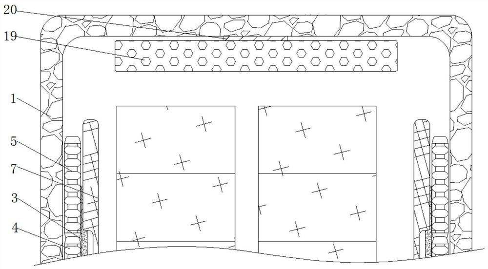
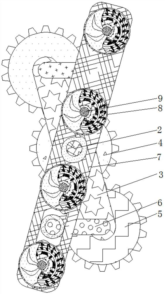
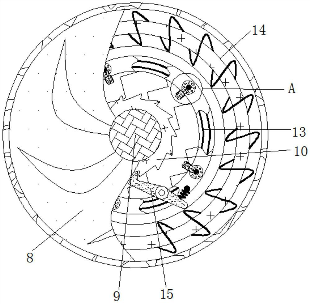

Embodiment Construction

[0025] The following will clearly and completely describe the technical solutions in the embodiments of the present invention with reference to the accompanying drawings in the embodiments of the present invention. Obviously, the described embodiments are only some, not all, embodiments of the present invention. Based on the embodiments of the present invention, all other embodiments obtained by persons of ordinary skill in the art without making creative efforts belong to the protection scope of the present invention.

[0026] see Figure 1-5 , an automatic heat dissipation and fire extinguishing device for an outdoor transformer box, comprising a box body 1, the inside of the box body 1 is movably connected with a rotating shaft-2, the outside of the rotating shaft-2 is fixedly connected with a connecting rod-3, and the inside of the box body 1 There is gear one 4 fixedly connected, two gears two 5 are meshed with the outside of gear one 4, connecting rod two 6 is movably co...


PUM


Abstract

The invention relates to the technical field of electric power and discloses an automatic heat dissipation and fire extinguishing device for an outdoor transformer box. The device comprises a box body, first rotating shafts are movably connected to the interior of the box body, first connecting rods are fixedly connected to the exteriors of the first rotating shafts correspondingly, first gears are fixedly connected to the inner side of the box body, and second gears are engaged to the exteriors of the first gears correspondingly. A second connecting rod is movably connected to the exterior of each second gear. Third connecting rods are movably connected to the ends, away from the corresponding second gears, of the second connecting rods correspondingly. Shells are fixedly connected to the exteriors of the third connecting rods correspondingly. A driving shaft is movably connected into each shell. Through the interaction among ratchet wheels, bimetallic strips, conductors, coils, clamping rods, second rotating shafts, third gears, fourth gears, dry powder chambers and switch assemblies, fire on an electric appliance element or a wiring position in the box body can be extinguished in time, so that electric appliances and the like in the box body are prevented from being seriously damaged by fire combustion; and influences of faults of the transformer box on the life of residents and enterprise production are reduced.

Description

technical field [0001] The invention relates to the field of electric power technology, in particular to an automatic heat dissipation and fire extinguishing device for an outdoor transformer box. Background technique [0002] A transformer box is a box in a power system where the voltage and current of electric energy are exchanged, concentrated and distributed. [0003] Due to the universal application of electric energy, the continuity of power supply has become the guarantee of people's life. However, due to the large changes in electricity consumption in different regions and time periods, the work load of the substation box is large, and there is often a phenomenon of overloading the substation box. In this way, the electrical components inside the transformer box will cause accidents due to aging or short circuit, resulting in the loss of public property, and the electrical components inside the transformer box will generate a lot of heat when they work for a long tim...

Claims


Application Information

Patent Timeline
Patent Type & Authority Applications(China)
IPC IPC(8): A62C3/16A62C35/08
CPCA62C3/16A62C35/08
Inventor 罗光才
Owner 罗光才
Learn More