
An adjustment method for a flexible adjustment system for power generation load of a multi-heat source cogeneration unit

A technology of cogeneration unit and power generation load, which can be applied to heating systems, heating methods, machines/engines, etc., and can solve the problems of limited electric load adjustable range, high heating energy consumption, and difficulty in power grid peak regulation. Achieve the effect of expanding the heating capacity and solving the shortage of heat sources

Active Publication Date: 2022-06-28
NORTH CHINA ELECTRIC POWER UNIV (BAODING)
View PDF25 Cites 0 Cited by
  • Summary
  • Abstract
  • Description
  • Claims
  • Application Information

AI Technical Summary

Problems solved by technology

A few days ago, my country's combined heat and power units accounted for 40% of the thermal power installed capacity. Most heating units mainly use steam extraction for heating. Restricted, making winter power grid peak shaving difficult
[0004] 2 The installed capacity of renewable energy in my country has increased rapidly, and the demand for grid connection has also increased the difficulty of peak regulation, and the difficulty of peak regulation in the power grid has limited the space for the acceptance of renewable energy.
[0006] 4Existing means of peak regulation, such as electric boilers, steam turbine high and low pressure bypass heating methods, etc., can increase the demand for deep peak regulation of the unit, but the energy is high in quality and low in use, and the heating energy consumption is high, so it is not energy-saving

Method used


Image

  • An adjustment method for a flexible adjustment system for power generation load of a multi-heat source cogeneration unit

Examples


Embodiment Construction

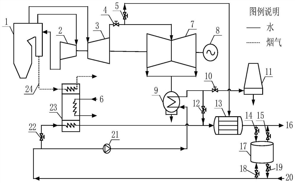
[0018] The present invention proposes a flexible power generation load adjustment system for a multi-heat source cogeneration unit. The multi-heat source heating system is composed of a conventional coal-fired power generation system and a multi-heat source cogeneration unit power generation load flexible adjustment system. The following describes this system with reference to the accompanying drawings. The invention is explained.

[0019] figure 1 Shown is the schematic diagram of the power generation regulation system of the multi-heat source cogeneration unit. The conventional coal-fired power generation system includes a boiler 1, a high-pressure cylinder 2, a medium-pressure cylinder 3, a low-pressure cylinder 7 and a generator 8 connected in series; wherein; the regulating valve 4 for the steam exhaust from the medium-pressure cylinder to the steam inlet flow of the low-pressure cylinder is connected to the low-pressure cylinder. Connection; medium pressure cylinder exh...


PUM


Abstract

The invention discloses a flexible regulation system for power generation load of multi-heat source heat and power cogeneration units, which belongs to the technical field of energy comprehensive utilization. The system is composed of conventional coal-fired power generation system and multi-heat source cogeneration unit generation load flexible adjustment system; multi-heat source cogeneration unit generation load flexible adjustment system includes flue gas low-temperature heat source heater, low-temperature heat source heater, high-temperature heat source heating device, heat storage heat source, heating network return water pipeline and heating network water supply pipeline; among them, the regulating valve of the medium-pressure cylinder exhaust steam to the low-pressure cylinder inlet steam flow of the conventional coal-fired power generation system is connected to the low-pressure cylinder; the medium-pressure cylinder exhaust valve is connected to the to a high temperature heat source heater. The heating heat source of the heating network water supply consists of a low-temperature heat source of flue gas, a low-temperature heat source of steam, a high-temperature heat source of steam and a heat storage heat source. The invention fully recycles and utilizes low-grade waste heat energy to expand heat supply capacity, couples and complements multiple heat sources, solves the problem of insufficient heat sources during deep peak regulation of units, and realizes active regulation of electrical loads.

Description

technical field [0001] The invention belongs to the technical field of comprehensive utilization of energy, and in particular relates to a system and method for flexibly adjusting the power generation load of a multi-heat source cogeneration unit. Background technique [0002] Cogeneration is a comprehensive utilization technology of energy, which realizes energy saving, improves the environment, and improves the living standards of urban residents; it plays an active role in solving the growing power supply and urban heating; cogeneration means that power plants not only produce electricity, but also It also uses the steam produced by the steam turbine generator to provide heat to the user. This method saves fuel compared with the method of separately producing electric energy and heat energy. The steam of cogeneration has no cooling loss, so the thermal efficiency can be increased by 80%. The above; but there is flexibility, and the following problems may occur: [0003] ...

Claims


Application Information

Patent Timeline
Patent Type & Authority Patents(China)
IPC IPC(8): F24D11/02F01D17/10F01D15/10F01K11/02
CPCF24D11/0235F01D17/10F01D15/10F01K11/02F24D2200/123F24D2200/18
Inventor 杜小泽杨勇平戈志华张尤俊徐磊卫慧敏杨志平
Owner NORTH CHINA ELECTRIC POWER UNIV (BAODING)
Learn More