Intelligent manufacturing equipment for improving textile drying efficiency by utilizing centrifugal force

A technology of intelligent manufacturing and textiles, applied in the field of textile fabrics, can solve the problems of uneven heating of textile fabrics, waste of time and resources, and lack of linkage, etc., to improve drying efficiency, reduce working time, and improve stability Effect

Inactive Publication Date: 2021-04-06
徐玉婷
View PDF0 Cites 2 Cited by
  • Summary
  • Abstract
  • Description
  • Claims
  • Application Information

AI Technical Summary

Problems solved by technology

[0003] However, when the heating equipment inside the drying box is used for a long time, there will be a situation. Because the textile fabric runs in a horizontal or U-shaped route inside the drying box, but the heating position is generally relatively fixed, it will cause the textile fabric to be very hot. It is easy to cause uneven heating. Not only that, there will be a lot of moisture inside the textile fabric after it has just been washed. Generally, the moisture is removed first when drying, and then placed in the drying box. Without linkage, this kind of processing technology will waste a lot of time and resources, the production cost will also increase, and the drying efficiency is not high. Therefore, an intelligent manufacturing equipment that uses centrifugal force to improve the drying efficiency of textiles came into being.

Method used


Image

  • Intelligent manufacturing equipment for improving textile drying efficiency by utilizing centrifugal force
  • Intelligent manufacturing equipment for improving textile drying efficiency by utilizing centrifugal force
  • Intelligent manufacturing equipment for improving textile drying efficiency by utilizing centrifugal force

Examples


Embodiment Construction

[0025] The following will clearly and completely describe the technical solutions in the embodiments of the present invention with reference to the accompanying drawings in the embodiments of the present invention. Obviously, the described embodiments are only some, not all, embodiments of the present invention. Based on the embodiments of the present invention, all other embodiments obtained by persons of ordinary skill in the art without making creative efforts belong to the protection scope of the present invention.

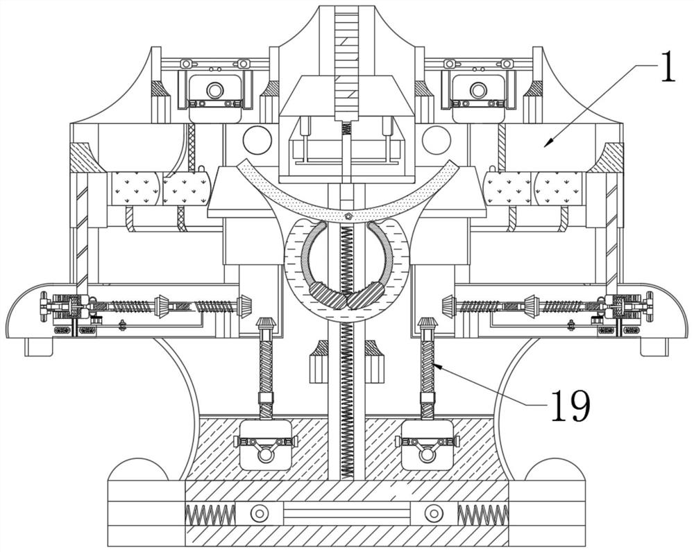
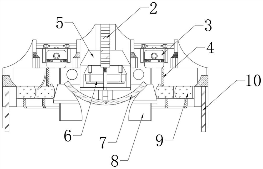
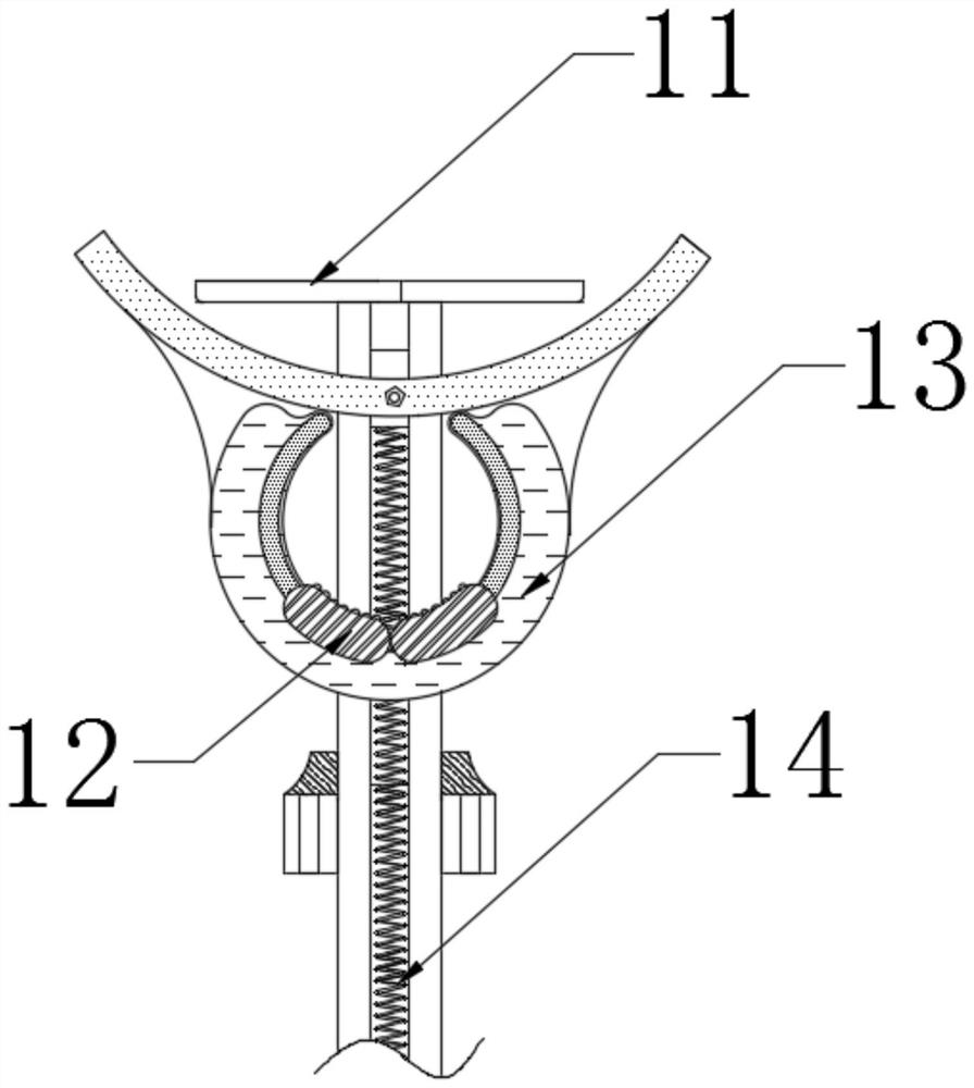
[0026] see Figure 1-5 :

[0027] An intelligent manufacturing device that uses centrifugal force to improve the drying efficiency of textiles, including a body 1, a main shaft 2 is movably connected to the middle of the body 1 and located inside the metal part 3, and a metal part 3 is movably connected to the outside of the main shaft 2 and located above the acceleration tube 4, This structure has stability and ease of use; the top of the main body 1 is mova...


PUM


Abstract

The invention relates to the technical field of textile fabrics, and discloses intelligent manufacturing equipment for improving textile drying efficiency by utilizing centrifugal force. The intelligent manufacturing equipment for improving the textile drying efficiency by utilizing the centrifugal force comprises a body, the top end of the body is movably connected with a main shaft, the outer side of the main shaft is movably connected with a metal piece, and the lower end of the metal piece is movably connected with an accelerating tube. According to the intelligent manufacturing equipment for improving the textile drying efficiency by utilizing the centrifugal force, the main shaft is powered on to operate and drives a bottom plate to operate along with the main shaft, certain centrifugal force is formed when the bottom plate rotates, the metal piece vibrates under the action of the centrifugal force and drives the accelerating tube to operate gradually, and a sliding plate drives a blocking piece to synchronously rotate anticlockwise; the blocking piece is composed of two same parts, the main shaft drives a round rod to operate synchronously, the round rod acts on a buckle in the middle of the blocking piece to be opened gradually, the blocking piece has the tendency of expanding outwards and pushes a diffusion disc to operate along with the blocking piece, and therefore a heating area of the equipment is increased, the drying use efficiency is improved, and the working time is shortened.

Description

technical field [0001] The invention relates to the technical field of textile fabrics, in particular to an intelligent manufacturing device that uses centrifugal force to improve the drying efficiency of textiles. Background technique [0002] The original meaning of textile is taken from the general term of spinning and weaving, but with the continuous development and improvement of the textile knowledge system and subject system, especially after the emergence of non-woven textile materials and three-dimensional composite weaving technologies, it is not only the traditional hand spinning And weaving, also including non-woven technology, modern three-dimensional weaving technology, modern electrostatic nano-netting technology and other clothing, industrial and decorative textiles, clothing, airbags and curtains and carpets in daily life are textile and The product of printing and dyeing technology, traditional textile fabric drying equipment mainly includes drying box and ...

Claims


Application Information

Patent Timeline
Patent Type & Authority Applications(China)
IPC IPC(8): D06B15/00D06B15/10
CPCD06B15/00D06B15/10
Inventor 徐玉婷
Owner 徐玉婷
Why Eureka
Try Eureka