
Liquefied gas bottle welding device and using method thereof

A technology of liquefied gas cylinders and welding devices, applied in auxiliary devices, welding equipment, auxiliary welding equipment, etc., can solve the problems of increasing safety hazards, reducing welding efficiency, and entanglement of liquefied gas pipelines, so as to avoid easy entanglement and improve convenience , the effect of convenient flipping

Pending Publication Date: 2021-04-06
湖南富佳钢瓶制造有限公司
View PDF17 Cites 0 Cited by
  • Summary
  • Abstract
  • Description
  • Claims
  • Application Information

AI Technical Summary

Problems solved by technology

[0004] Liquefied gas needs to be stored in liquefied gas cylinders for transportation and sales. Liquefied gas cylinders need to be welded during the production process. However, the traditional welding method is usually to place the liquefied gas cylinders on the ground and manually weld them. The liquefied gas cylinder moves back and forth, and the long liquefied gas pipeline is prone to entanglement during manual welding, and even causes damage to the liquefied gas pipeline, which increases safety hazards. At the same time, it is not convenient to place the liquefied gas cylinder on the ground. The bottle is adjusted, which is inconvenient for the staff to weld and greatly reduces the welding efficiency

Method used


Image

  • Liquefied gas bottle welding device and using method thereof
  • Liquefied gas bottle welding device and using method thereof
  • Liquefied gas bottle welding device and using method thereof

Examples


Embodiment Construction

[0042] The following will clearly and completely describe the technical solutions in the embodiments of the present invention with reference to the accompanying drawings in the embodiments of the present invention. Obviously, the described embodiments are only some, not all, embodiments of the present invention. Based on the embodiments of the present invention, all other embodiments obtained by persons of ordinary skill in the art without making creative efforts belong to the protection scope of the present invention.

[0043]see Figure 1-Figure 7 , the present invention provides a technical solution:

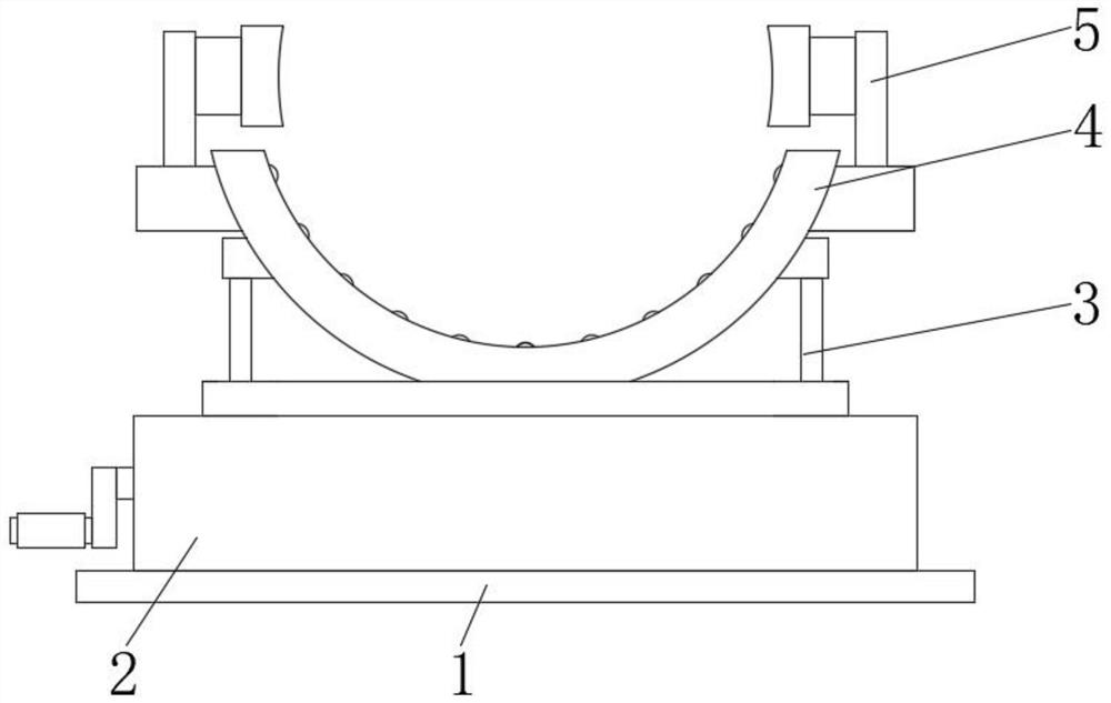
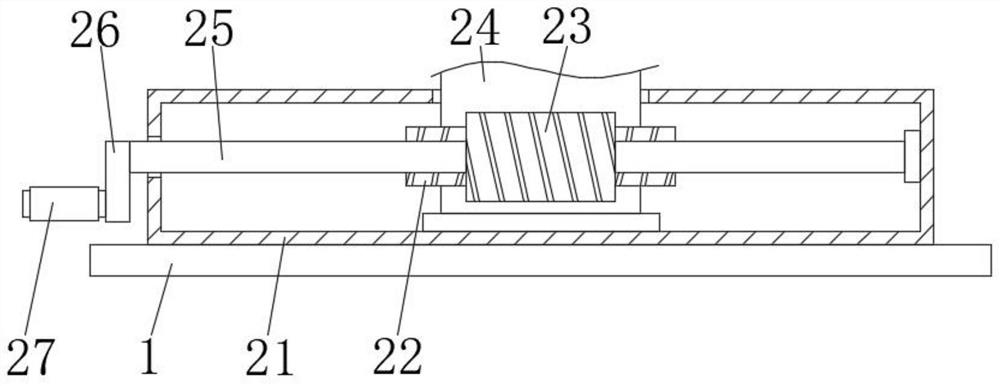
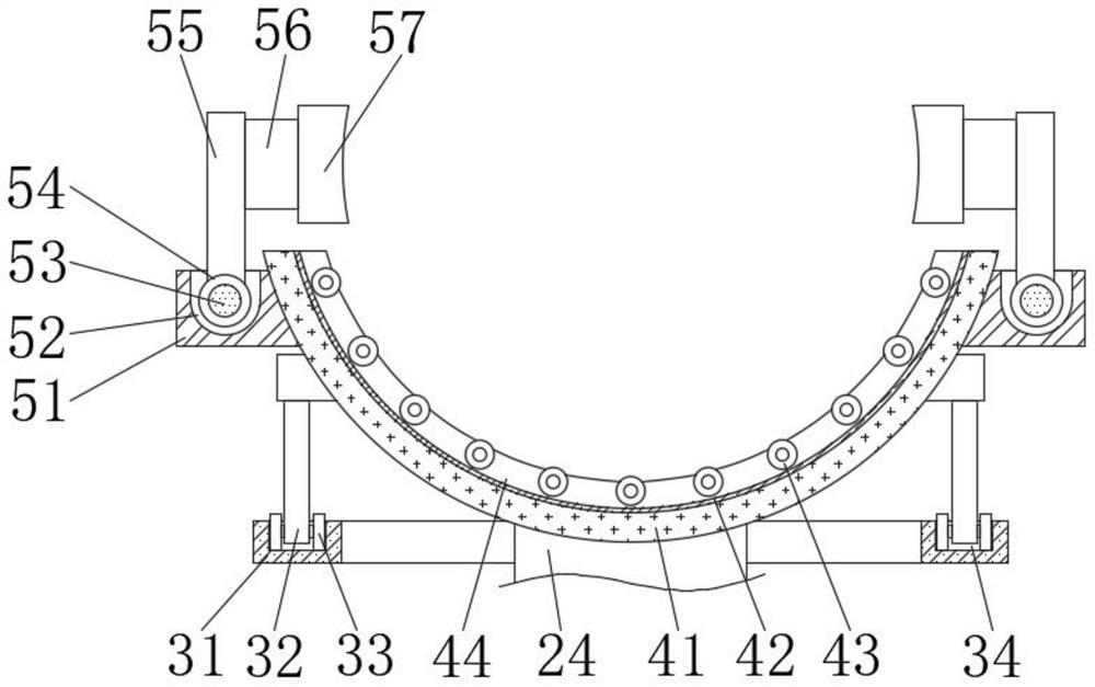
[0044] A liquefied gas cylinder welding device, comprising: a base 1, a rotating mechanism 2, a supporting mechanism 3, an overturning mechanism 4 and a clamping mechanism 5, the rotating mechanism 2 is fixedly installed on the top of the base 1, and the number of clamping mechanisms 5 is two , two clamping mechanisms 5 are respectively welded to the top of both sides of the...


PUM

PropertyMeasurementUnit
Rotation angleaaaaaaaaaa

Abstract

The invention discloses a liquefied gas bottle welding device and a using method thereof. The liquefied gas bottle welding device comprises a base, a rotating mechanism, a supporting mechanism, a turnover mechanism and two clamping mechanisms; and the rotating mechanism is fixedly installed at the top of the base, the two clamping mechanisms are welded to the tops of the two sides of the turnover mechanism correspondingly, and the supporting mechanism is installed at the top of the rotating mechanism. According to the scheme, a rotary disc is rotated through a grip, the turnover mechanism in an inner cavity of a fixing box can be rotated, then horizontal rotation of a liquefied gas bottle installed in an inner cavity of the turnover mechanism is achieved, and the liquefied gas bottle can be turned over in an inner cavity of a supporting seat by separating the two clamping mechanisms towards the outer side; and the situation that a worker needs to move back and forth when a liquefied gas bottle is welded can be effectively avoided, then the situation that a liquefied gas pipeline is prone to twisting is avoided, meanwhile, the liquefied gas bottle can be turned over very conveniently, and the efficiency during welding is greatly improved.

Description

technical field [0001] The invention relates to the technical field of liquefied gas storage, in particular to a liquefied gas bottle welding device and a use method thereof. Background technique [0002] Liquefied petroleum gas is a colorless volatile liquid obtained by liquefying natural gas or petroleum under pressure and cooling in an oil refinery. It is highly prone to spontaneous combustion. When its content in the air reaches a certain concentration range, it can explode when it encounters an open flame. Using liquefied petroleum gas as fuel, because of its high calorific value, no smoke, no carbon residue, easy operation and use, has widely entered the field of people's lives. In addition, liquefied petroleum gas is also used for cutting metals, baking agricultural products and roasting industrial kilns, etc. [0003] The liquefied gas tank refers to the storage tank used to store liquefied gas. When there is liquefied gas inside, the pressure is very high, and a s...

Claims


Application Information

Patent Timeline
IPC IPC(8): B23K37/00B23K37/047B23K101/12
CPCB23K37/00B23K37/047B23K2101/12
Inventor 朱光谦胡林明周四元
Owner 湖南富佳钢瓶制造有限公司
Learn More