
Brake pad stamping die with good heat dissipation performance

A technology for stamping dies and brake pads, used in forming tools, manufacturing tools, vehicle parts, etc., which can solve problems such as reducing the durability of parts, accelerating machine aging, and failing to meet processing needs.

Inactive Publication Date: 2021-04-06
ANHUI GUIDA AUTO PARTS
View PDF6 Cites 0 Cited by
  • Summary
  • Abstract
  • Description
  • Claims
  • Application Information

AI Technical Summary

Problems solved by technology

[0003] Brake pads are commonly used parts in vehicle processing. During the processing of brake pads, molds are used for the grooves. During the stamping process, the temperature inside the mold will increase, which may reduce the durability of the parts and make the lubricating oil consumed too quickly. Accelerate the aging of the machine and cannot meet the processing needs

Method used


Image

  • Brake pad stamping die with good heat dissipation performance
  • Brake pad stamping die with good heat dissipation performance
  • Brake pad stamping die with good heat dissipation performance

Examples


Embodiment 1

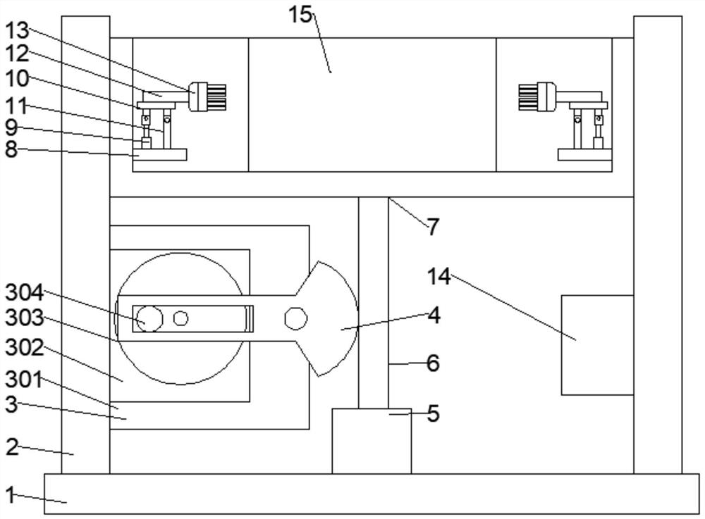
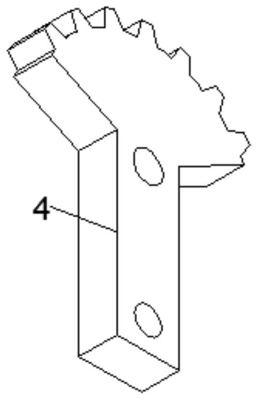
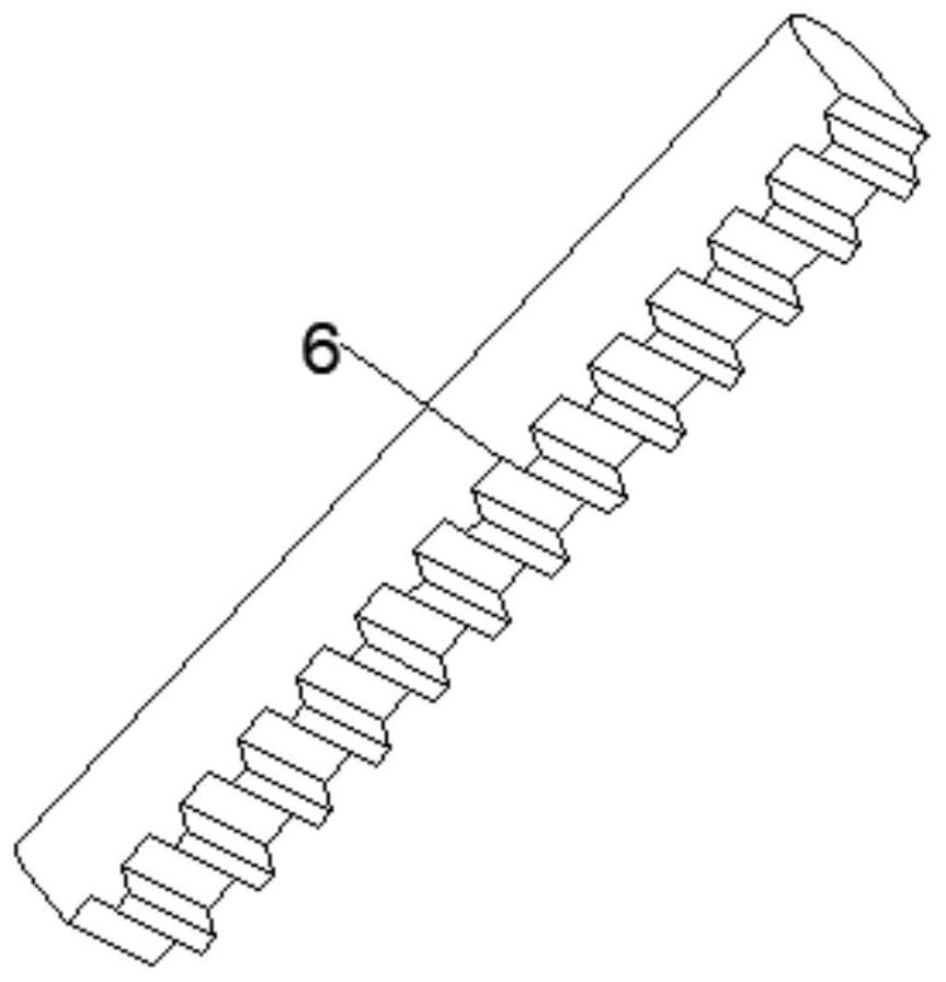
[0021] Example 1: Please refer to Figure 1~3 , in an embodiment of the present invention, a brake pad stamping die with good heat dissipation includes a bottom plate 1 and a support column 2, the support column 2 is fixedly connected to the top of both sides of the bottom plate 1, and the drive mechanism 3 is fixedly connected to the bottom of the left support column 2 , the drive mechanism 3 is rotatably connected with a sector gear handle 4 with a closed square chute at the left end, a fixed block 5 is fixedly connected above the middle part of the bottom plate 1, and the middle part of the fixed block 5 is slidably connected with a left side meshing with the right end of the sector gear handle 4 The sliding rack 6, the upper end of the sliding rack 6 is fixedly connected with the mounting frame 7 slidingly connected with the supporting column 2, the fixing plate 8 is fixedly connected under the two sides of the mounting frame 7, and the electric push rod 9 is fixedly connec...

Embodiment 2

[0026] Embodiment 2: This embodiment is a further improvement of the previous embodiment: the lower end of the right support column 2 is fixedly connected with a controller 14, which is convenient for controlling the operation of the motor 302 and the electric push rod 9 .

[0027] The working principle of the present invention is: the motor 302 drives the turntable 303 to rotate, and then drives the sliding column 304 to rotate, and then drives the sector gear handle 4 to swing up and down through the sliding of the sliding column 304 in the closed square chute, and then drives the sliding teeth through the meshing of the teeth The bar 6 slides up and down, and then realizes the adjustment of the height position of the mounting frame 7; the electric push rod 9 drives the swing plate 10 to swing, and then drives the connecting shaft 12 to swing, and then drives the refrigerator 13 to swing, thereby fully cooling and dissipating heat inside the mounting frame 7, Effectively avoi...


PUM


Abstract

The invention discloses a brake pad stamping die with good heat dissipation performance, and relates to a brake pad stamping die. The brake pad stamping die comprises a bottom plate, wherein supporting stand columns are fixedly connected to the upper portions of the two sides of the bottom plate; a driving mechanism is fixedly connected to the lower portion of the supporting stand column on the left side; the driving mechanism is rotationally connected with a fan-shaped gear rotating handle; a fixing block is fixedly connected to the upper portion of the middle of the bottom plate; a sliding rack is connected to the middle of the fixing block in a sliding mode; the upper end of the sliding rack is fixedly connected with a mounting frame; fixing plates are fixedly connected to the lower portions of the two sides of the mounting frame; an electric push rod is fixedly connected to the upper portion of one side of each fixing plate; the upper end of each electric push rod is rotationally connected with a swing plate; the lower portion of the other side of each swing plate is rotationally connected with a vertical rod fixedly connected to the upper portion of the corresponding fixing plate; and a connecting shaft is fixedly connected to the upper portion of each swing plate. The electric push rods drive the swing plates to swing, then the connecting shafts are driven to swing, then a refrigerator is driven to swing, so that the interior of the mounting frame is fully cooled and subjected to heat dissipation, and a series of defects caused by too high temperature are effectively avoided.

Description

Technical field [0001] The invention relates to a brake pad stamping die, specifically a brake pad stamping die with good heat dissipation properties. Background technique [0002] Molds refer to various molds and tools used in industrial production to obtain the required products by injection molding, blow molding, extrusion, die-casting or forging, smelting, stamping and other methods. In short, a mold is a tool used to make shaped objects. This tool is composed of various parts, and different molds are composed of different parts. It mainly realizes the processing of the shape of the object by changing the physical state of the molded material, and is known as the "Mother of Industry". [0003] Brake pads are commonly used parts in vehicle processing. During the processing of brake pads, molds are used for slotting. During the stamping process, the temperature inside the mold will increase, which may reduce the durability of the parts and cause the lubricating oil to be ...

Claims


Application Information

Patent Timeline
IPC IPC(8): B21D37/10B21D37/16B21D53/88
CPCB21D37/10B21D37/16B21D53/88
Inventor 林和平
Owner ANHUI GUIDA AUTO PARTS
Learn More