
Vibrating screen for buffering ore impact force

A technology of impact force and vibrating screen, which is applied in the field of mining machinery, can solve the problems of reducing the service life of the vibrator, strong vibration of the vibrating screen, and damage to the motor, and achieve the effects of reducing the impact force, increasing the blanking time, and weakening the impact force

Inactive Publication Date: 2021-04-06
刘怀欣
View PDF0 Cites 0 Cited by
  • Summary
  • Abstract
  • Description
  • Claims
  • Application Information

AI Technical Summary

Problems solved by technology

[0003] At present, vibrating screens are used in the processing of ore in the market. When the existing vibrating screen screens the ore, because the material of the ore is relatively hard, the vibrating screen will bear the impact of the ore when transporting the ore. It will cause the vibration of the vibrating screen to be relatively strong, and the motor will also be subject to strong vibration, the motor will be easily damaged, and the service life of the vibrator will be greatly reduced.

Method used


Image

  • Vibrating screen for buffering ore impact force
  • Vibrating screen for buffering ore impact force
  • Vibrating screen for buffering ore impact force

Examples


Embodiment 1

[0030] Such as figure 1 and Figure 3-5 displayed in:

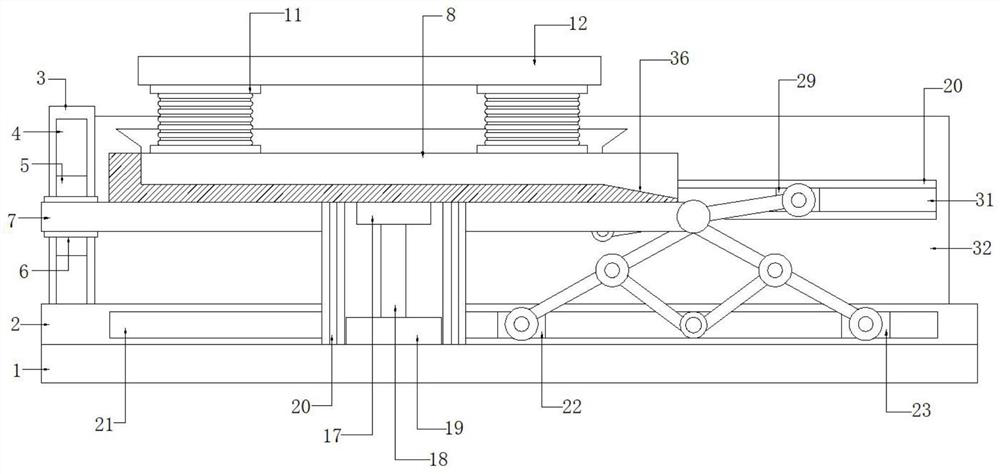
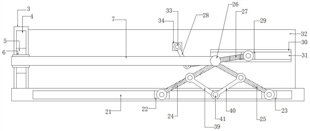
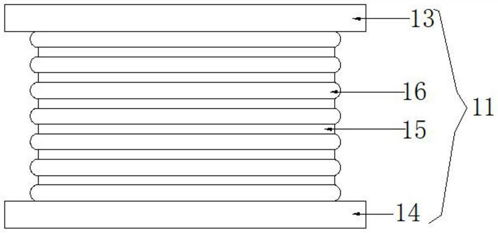
[0031]The present invention provides a vibrating screen suitable for cushioning the impact force of ore. Its structure includes a support base 1, a support column 2 is provided on the top side of the support base 1, and a vertical plate 3 is provided at the top end of the support column 2. , the side of the riser 3 is provided with a chute 4, the chute 4 is provided with a slider 5 matching with the chute 4, and the slider 5 is far away from the chute One side of groove one 4 is provided with fixed plate one 6, described fixed plate one 6 and one side away from described slide block one 5 are provided with horizontal plate 7, and the top of described horizontal plate 7 is provided with collecting bin 8, so The collecting chamber 8 is provided with a collecting chamber 9, and the collecting chamber 9 is provided with a discharge port 10 at one end away from the vertical plate 3, and the four ends around the top of the co...

Embodiment 2

[0034] Such as figure 1 , 6 displayed in:

[0035] The present invention provides a vibrating screen suitable for cushioning the impact force of ore. Its structure includes a support base 1, a support column 2 is provided on the top side of the support base 1, and a vertical plate 3 is provided at the top end of the support column 2. , the side of the riser 3 is provided with a chute 4, the chute 4 is provided with a slider 5 matching with the chute 4, and the slider 5 is far away from the chute One side of groove one 4 is provided with fixed plate one 6, described fixed plate one 6 and one side away from described slide block one 5 are provided with horizontal plate 7, and the top of described horizontal plate 7 is provided with collecting bin 8, so The collecting chamber 8 is provided with a collecting chamber 9, and the collecting chamber 9 is provided with a discharge port 10 at one end away from the vertical plate 3, and the four ends around the top of the collecting ch...

Embodiment 3

[0038] Such as Figure 1-2 displayed in:

[0039] The present invention provides a vibrating screen suitable for cushioning the impact force of ore. Its structure includes a support base 1, a support column 2 is provided on the top side of the support base 1, and a vertical plate 3 is provided at the top end of the support column 2. , the side of the riser 3 is provided with a chute 4, the chute 4 is provided with a slider 5 matching with the chute 4, and the slider 5 is far away from the chute One side of groove one 4 is provided with fixed plate one 6, described fixed plate one 6 and one side away from described slide block one 5 are provided with horizontal plate 7, and the top of described horizontal plate 7 is provided with collecting bin 8, so The collecting chamber 8 is provided with a collecting chamber 9, and the collecting chamber 9 is provided with a discharge port 10 at one end away from the vertical plate 3, and the four ends around the top of the collecting cham...


PUM


Abstract

The invention discloses a vibrating screen for buffering ore impact force. The vibrating screen for buffering the ore impact force comprises a supporting base, a supporting column is arranged on the side edge of the top of the supporting base, a vertical plate is arranged at one end of the top of the supporting column, a first sliding groove is formed in the side edge of the vertical plate, a first sliding block matched with the first sliding groove is arranged in the first sliding groove, a first fixing plate is arranged on the side, away from the first sliding groove, of the first sliding block, a transverse plate is arranged on the side, away from the first sliding block, of the first fixing plate, a collecting bin is arranged at the top of the transverse plate, a collecting cavity is formed in the collecting bin, a discharging port is formed in the end, away from the vertical plate, of the collecting cavity, shock insulation supports are arranged at the four ends of the periphery of the top of the collecting bin, a screen is arranged at the tops of the shock insulation supports, and each shock insulation support is composed of an upper base plate, a lower base plate, a plurality of steel plates and a rubber layer, so that the impact force generated by ore on the collecting bin is effectively reduced, the service life of the device is prolonged, a vibrator is effectively protected, and the propagation of noise is reduced.

Description

technical field [0001] The invention relates to the technical field of mining machinery, in particular to a vibrating screen for buffering the impact force of ore. Background technique [0002] Ore refers to mineral aggregates from which useful components can be extracted or which have certain properties that can be utilized. It can be divided into metallic minerals and non-metallic minerals. The unit content of useful components (elements or minerals) in ores is called ore grade. Precious metal ores such as gold and platinum are expressed in grams per ton, and other ores are usually expressed in percentages. The ore grade is often used to measure the value of ore, but the composition and harmful impurities of the gangue (useless minerals in the ore or minerals with very little useful content that cannot be used) and harmful impurities in the ore also affect the value of the ore. [0003] At present, vibrating screens are used in the processing of ore in the market. When t...

Claims


Application Information

Patent Timeline
IPC IPC(8): B07B1/28B07B1/42B07B1/46G10K11/16F16F15/08
CPCB07B1/28B07B1/42B07B1/46F16F15/08G10K11/16
Inventor 刘怀欣
Owner 刘怀欣
Learn More