Method for preparing propionic acid by catalysis of lactic acid

A technology for the preparation of catalysis and propionic acid, which is applied in the preparation of carboxylate, chemical instruments and methods, and the preparation of organic compounds. It can solve the problems of great influence on stirring efficiency, complex equipment structure, and high sealing requirements, and achieve stirring without dead ends. , Stirring structure is simple, the effect of improving the stirring effect

Active Publication Date: 2022-04-22
河南金丹乳酸科技股份有限公司
View PDF0 Cites 0 Cited by
  • Summary
  • Abstract
  • Description
  • Claims
  • Application Information

AI Technical Summary

Problems solved by technology

[0002] Propionic acid has a wide range of uses, mainly used as esterification agent, plasticizer, chemical reagent and food raw materials, etc.; when preparing propionic acid through lactic acid catalysis, it is necessary to put lactic acid, catalyst, reducing agent and other raw materials into the hydrothermal reactor Heating inside to prepare propionic acid. Most of the existing hydrothermal reactors use magnetic stirring, motor-driven stirring, etc. in the stirring method. The stirring efficiency of magnetic stirring is greatly affected by the magnetic force, and the stirring effect is not ideal. Stirring requires high sealing requirements on the stirring shaft, resulting in complex equipment structure and high cost; and because the hydrothermal reactor needs to withstand high pressure, its wall thickness is relatively large, resulting in low heat transfer efficiency and slow cooling, which affects the preparation speed. After the reaction, it is necessary to filter the reaction product to remove the catalyst. Filtration for a long time will block the pores of the filter screen, resulting in a decrease in filtration efficiency.

Method used


Image

  • Method for preparing propionic acid by catalysis of lactic acid
  • Method for preparing propionic acid by catalysis of lactic acid
  • Method for preparing propionic acid by catalysis of lactic acid

Examples


Embodiment Construction

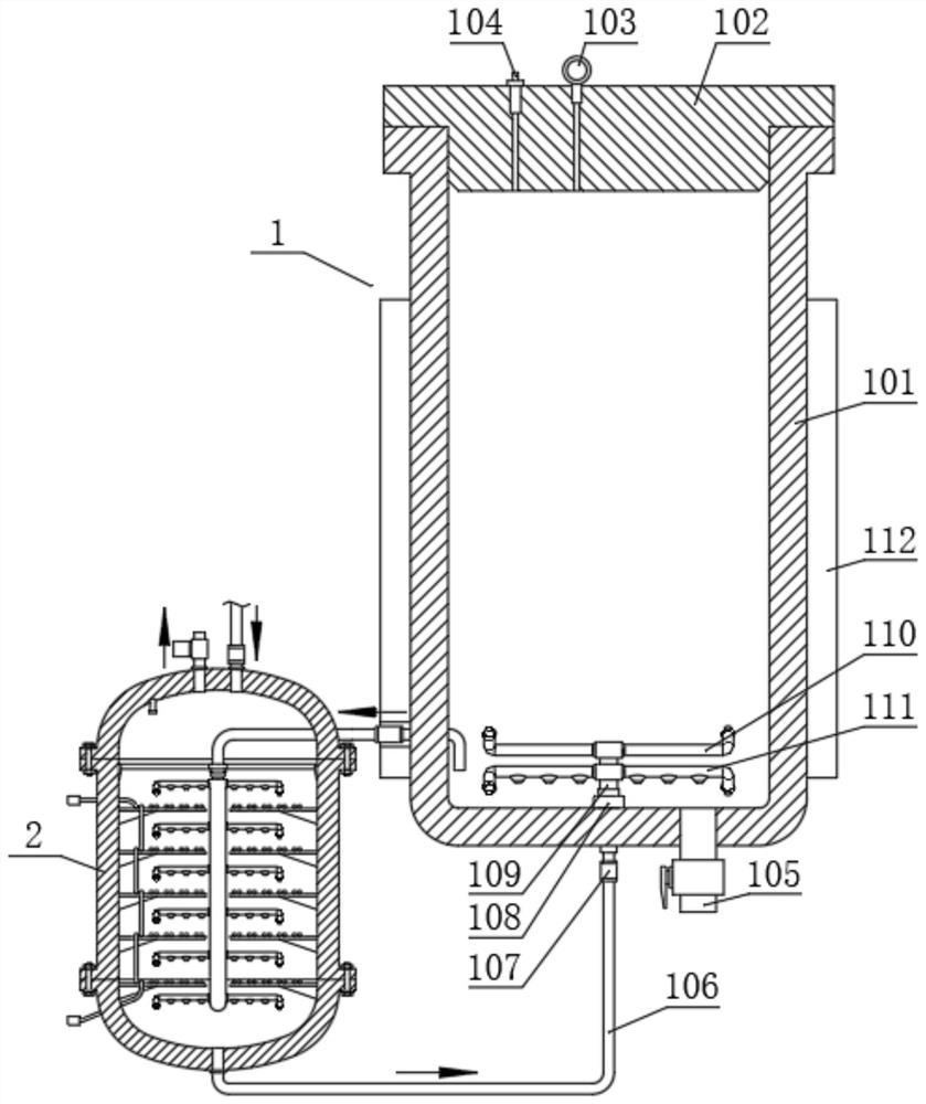
[0027] Lactic acid is catalyzed to prepare propionic acid method, comprises the following steps:

[0028] Step A: adding materials into the reaction tank 101 of the reaction component 1 of the preparation device, and closing the sealing cover 102 of the reaction tank 101;

[0029] Step B: Turn on the heating assembly 112 of the reaction assembly 1 to heat the material:

[0030] Step C: The material is reacted in the reaction tank 101:

[0031] Step D: After the reaction is completed, the sealing cover 102 is opened, and the reacted material is discharged from the discharge pipe 105 opened at the bottom of the reaction tank 101 .

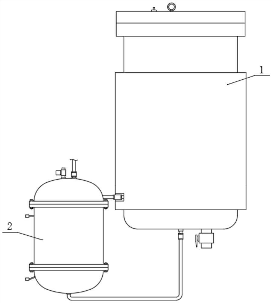
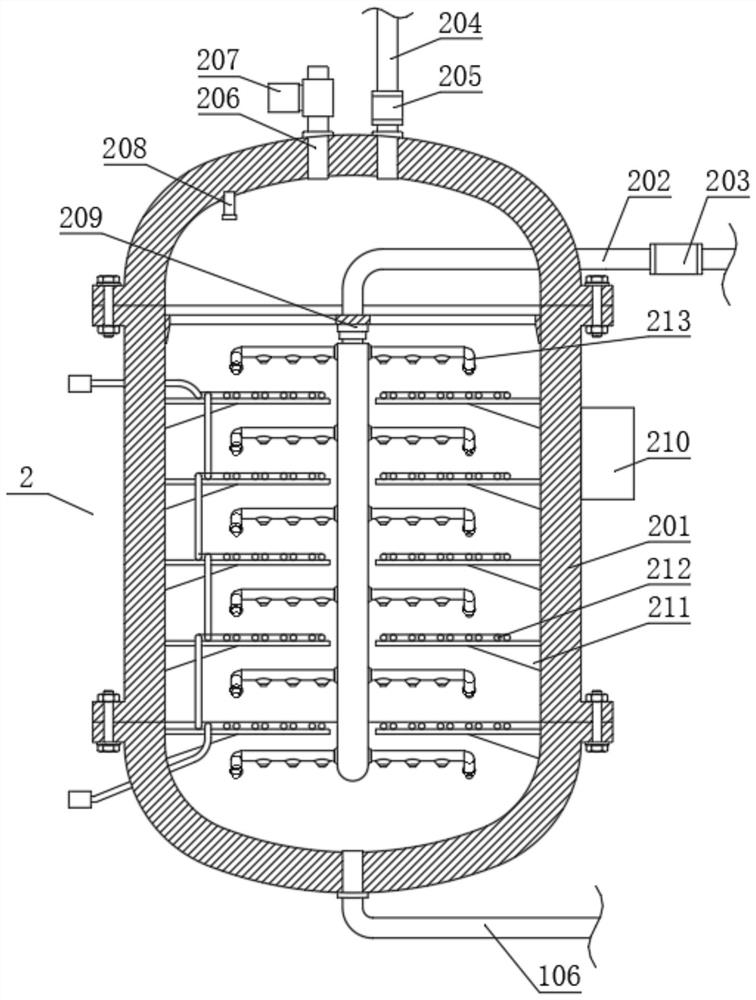
[0032]see figure 1 , the preparation device also includes a reaction assembly 1, a circulation assembly 2 and a filter assembly 3, the bottom of the reaction assembly 1 is communicated with a return pipe 106, and the reaction assembly 1 is communicated with the bottom of the circulation assembly 2 through the return pipe 106, as figure 2 As shown...


PUM


Abstract

The invention discloses a method for preparing propionic acid by catalyzing lactic acid, which comprises the following steps: firstly, adding materials into the reaction tank of the reaction component of the preparation device respectively, closing the sealing cover of the reaction tank, and then opening the heating component of the reaction component to heat the material, The material is reacted in the reaction tank, and when the reaction is completed, the sealing cover is opened, and the reacted material is discharged from the discharge pipe opened at the bottom of the reaction tank. In the present invention, by setting the reaction component and the circulation component, the liquid in the circulation tank flows into the reaction tank. When the liquid passes through the rotary nozzle and enters the upper rotary nozzle and the first lower rotary nozzle, it rotates under the thrust of the liquid ejection. The second Rotate the nozzle once to rotate and spray the liquid downward, and the sprayed liquid is sprayed to the bottom of the reaction tank to accelerate the flow rate of the liquid at the bottom of the reaction tank, so as to avoid catalysts, reducing agents, etc. from sinking to the bottom.

Description

technical field [0001] The invention relates to the technical field of chemical equipment. Specifically, it is a method for preparing propionic acid by catalyzing lactic acid. Background technique [0002] Propionic acid has a wide range of uses, mainly used as esterification agent, plasticizer, chemical reagent and food raw materials, etc.; when preparing propionic acid through lactic acid catalysis, it is necessary to put lactic acid, catalyst, reducing agent and other raw materials into the hydrothermal reactor Heating inside to prepare propionic acid. Most of the existing hydrothermal reactors use magnetic stirring and motor-driven stirring in the stirring methods. The stirring efficiency of magnetic stirring is greatly affected by the magnetic force, and the stirring effect is not ideal. However, the motor-driven Stirring requires high sealing requirements on the stirring shaft, resulting in complex equipment structure and high cost; and because the hydrothermal reacto...

Claims


Application Information

Patent Timeline
Patent Type & Authority Patents(China)
IPC IPC(8): B01J8/08B01J19/00B01J19/24B01D29/33B01D29/64C07C51/377C07C53/122
CPCB01J8/08B01J8/087B01J19/0053B01J19/0013B01J19/24B01D29/33B01D29/6423B01D29/6407C07C51/377C07C53/122Y02P20/141
Inventor 石从亮崔耀军师媛媛文倩顾永华张树银李艳坤楚慧灵刘清华郭廷刘玉洁王庆源毛洪涛王文亮
Owner 河南金丹乳酸科技股份有限公司
Why Eureka
Try Eureka