A kind of chip eutectic welding equipment and eutectic welding method
A eutectic welding and chip technology, applied in cleaning methods and utensils, chemical instruments and methods, cleaning methods using tools, etc., can solve problems such as inability to clean and collect, achieve cleaning and maintenance, avoid tin waste, and reduce processing. cost effect
- Summary
- Abstract
- Description
- Claims
- Application Information
AI Technical Summary
Problems solved by technology
Method used
Image
Examples
Embodiment 1
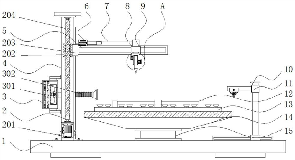
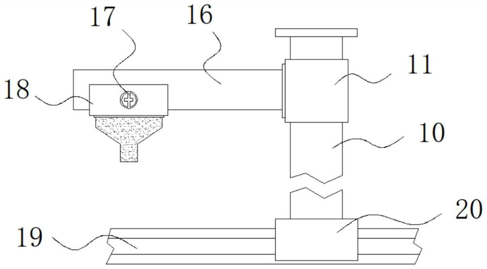
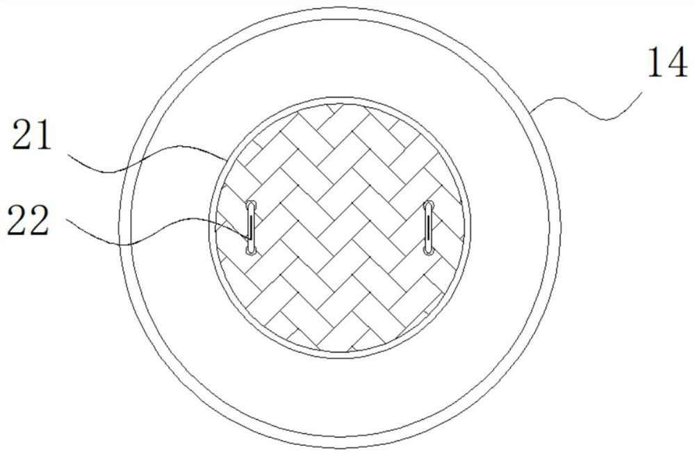
[0035] Example 1: See Figure 1-6, a chip eutectic welding equipment, including a base 1 and a column 4, one side of the top of the base 1 is fixedly connected with a column 4, the interior of the column 4 is provided with an adjustment mechanism 2, and one side of the column 4 is fixedly connected with a dust suction mechanism 3 , the other side of the column 4 is provided with a cross bar 5, one side of the top of the cross bar 5 is fixedly connected with an electric push rod 6, the model of the electric push rod 6 is IP800, and the output end of the electric push rod 6 is fixedly connected with a telescopic rod 7. One end of the crossbar 5 is provided with a first slider 8, the bottom end of the first slider 8 is fixedly connected with a replacement structure 9, the top end of the base 1 is fixedly connected with a rotating shaft 15, and the top end of the rotating shaft 15 is fixedly connected with a collecting tray 14 , the top of the collection tray 14 is provided with a...
Embodiment 2
[0040] Embodiment 2: Adjusting mechanism 2 is made up of servo motor 201, driving block 202, connecting block 203 and threaded rod 204, and threaded rod 204 is arranged on the inside of column 4, and the bottom end of threaded rod 204 is fixedly connected with servo motor 201, and this servo The model of the motor 201 is FLSC-67, the external movable part of the threaded rod 204 is connected with the driving block 202, and one side of the driving block 202 is fixedly connected with the connecting block 203;
[0041] One side of the connection block 203 is fixedly connected to one side of the cross bar 5, and the output end of the servo motor 201 is fixedly connected to the bottom end of the threaded rod 204 through a coupling;
[0042] Specifically, such as figure 1 As shown, since the device needs to process and weld different chips, the servo motor 201 at the bottom end of the column 4 is used to drive the threaded rod 204 to perform forward and reverse rotation, and the dri...
Embodiment 3
[0043] Embodiment 3: Dust suction mechanism 3 is made up of dust collection box 301, dust suction pipe 302, filter screen 303, filter agent 304 and blower fan 305, and dust collection box 301 is fixedly connected on one side of column 4, and the inside of dust collection box 301 One side is fixedly connected with a fan 305, the model of the fan 305 is DF, the other side inside the dust box 301 is fixedly connected with a filter screen 303, the inside of the dust box 301 is fixedly connected with a filter 304, and the inside of the dust box 301 One side is fixedly connected with a dust suction pipe 302;
[0044] One side of the dust suction pipe 302 runs through one side of the dust collecting box 301 and is fixedly connected to the input end of the fan 305;
[0045] Specifically, such as figure 1 and Figure 4 As shown, a specific solder paste is needed when soldering the chip, and the solder paste will produce some pungent gases during processing. By installing a dust box 3...
PUM
 Abstract
Description
Claims
Application Information
 - R&D
- Intellectual Property
- Life Sciences
- Materials
- Tech Scout
- Unparalleled Data Quality
- Higher Quality Content
- 60% Fewer Hallucinations
Browse by: Latest US Patents, China's latest patents, Technical Efficacy Thesaurus, Application Domain, Technology Topic, Popular Technical Reports.
© 2025 PatSnap. All rights reserved.Legal|Privacy policy|Modern Slavery Act Transparency Statement|Sitemap|About US| Contact US: help@patsnap.com


