
Steel wire production line feeding machining device

A processing device and production line technology, applied in the direction of conveying filamentous materials, thin material handling, transportation and packaging, etc., can solve problems such as the inability to achieve high-efficiency rolling work, the inability to guarantee the quality of processing, and the inability to achieve automatic adjustment. , to achieve the effect of practical saving, high practicability and high degree of automation

Pending Publication Date: 2021-04-02
王玉彬
View PDF5 Cites 3 Cited by
  • Summary
  • Abstract
  • Description
  • Claims
  • Application Information

AI Technical Summary

Problems solved by technology

Such a design can realize the coiling of steel wire, but the existence of a separate coiling mechanism determines that it cannot achieve high-efficiency coiling work, nor can it guarantee the quality of processing. During the coiling process, due to the wear and tear of the clamping steel wire and the inability to maintain a sufficient distance after the processing is completed to safely remove the finished product, it is also impossible to realize automatic adjustment to suit the coiling of steel wire coils of different diameters

Method used


Image

  • Steel wire production line feeding machining device
  • Steel wire production line feeding machining device
  • Steel wire production line feeding machining device

Examples


Embodiment Construction

[0024] The technical solutions of the present invention will be further specifically described below through the embodiments and in conjunction with the accompanying drawings. In the following description, many specific details are set forth in order to fully understand the present invention, but the present invention can be implemented in many other ways different from those described here, and those skilled in the art can do similar Modifications, and therefore the present invention is not limited to the specific examples disclosed below.

[0025] In the description of the present invention, it should be noted that the orientation or positional relationship indicated by the terms "up", "down", "front", "rear", "left", "right" etc. are based on the Orientation or positional relationship, or the orientation or positional relationship that the inventive product is usually placed in use, is only for the convenience of describing the present invention and simplifying the descript...


PUM


Abstract

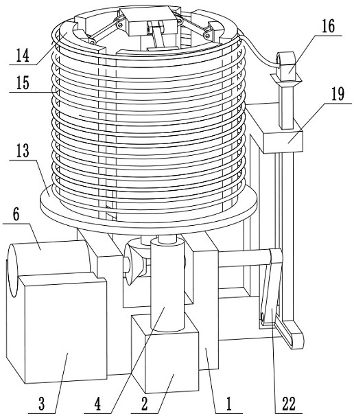
The invention discloses a steel wire production line feeding machining device. The steel wire production line feeding machining device comprises a finished product lifting device comprises finished product lifting device lifting sleeves, a bevel gear set, a driving motor, finished product lifting device lifting rods, a radius conversion device lower mounting plate, radius conversion device inner supporting rods, a radius conversion device hinging welding table, a winding barrel, a steel wire, a steel wire feeding hole, a steel wire up-down feeding rod, a steel wire feeding device crank, a steel wire feeding device connecting rod and a lifting hydraulic cylinder. According to the steel wire production line feeding machining device, the motor transmits power to a up-down feeding device and the winding barrel through a transmission device composed of three bevel gears to achieve rotary winding of the winding barrel, radius conversion of the winding barrel is achieved through lifting of ahydraulic rod, and after winding is completed, a wound steel wire coil can be conveniently taken down through radius conversion of the winding barrel, a finished product is lifted and sent out of thewinding barrel through a finished product lifting device, the other bevel gear drives the up-down feeding device to achieve up-down moving feeding of the steel wire on one side of the winding barrel,and then the steel wire is evenly wound on the winding barrel.

Description

technical field [0001] The invention relates to the technical field of processing machinery, in particular to a feeding and processing device for a steel wire production line. Background technique [0002] Winding and coiling steel wire is an indispensable process of modern raw material processing. The steel wire feeding mechanism on the market is generally designed to manually clamp one end of the main steel wire at one end, and the motor directly drives the coiling mechanism to complete coiling and then Manually take the finished product. Such a design can realize the coiling of steel wire, but the existence of a separate coiling mechanism determines that it cannot achieve high-efficiency coiling work, nor can it guarantee the quality of processing. During the coiling process, the wear caused by the clamping steel wire and the inability to maintain a sufficient distance after the processing is completed to safely remove the finished product, and it is impossible to realiz...

Claims


Application Information

Patent Timeline
Patent Type & Authority Applications(China)
IPC IPC(8): B65H54/40B65H54/28
CPCB65H54/40B65H54/28
Inventor 王玉彬高元武
Owner 王玉彬
Learn More