Automobile rear anti-collision beam connecting structure and rear anti-collision beam mounting method

A rear anti-collision beam and connection structure technology, applied to bumpers and other directions, can solve problems such as inconvenient glue application for workers, increased cost of rear floor molds, and complicated flanging molding, so as to avoid the risk of poor sealing, reduce weight and Cost, simple effect of flanging forming

Active Publication Date: 2021-04-02
BAIC MOTOR CORP LTD
View PDF7 Cites 1 Cited by
  • Summary
  • Abstract
  • Description
  • Claims
  • Application Information

AI Technical Summary

Problems solved by technology

Since the end plate of the rear longitudinal beam is on the inner side of the outer panel of the rear wall, in order to improve the bending and torsional rigidity of the rear wall and avoid four-layer welding, the end plate of the rear longitudinal beam protrudes for welding with the inner panel of the rear wall and the outer panel of the rear wall. Therefore, it is necessary to use sealant to add a sealing process. It is inconvenient for workers to apply glue here, and the probability of poor sealing is high. At the same time, the rear floor needs to make avoidance bosses to avoid the connection bolts of the rear anti-collision beam, so that the flanging can be formed. It is more complicated and needs to add a sequence of molds, so the mold cost is higher; in addition, there is excessive fillet between the end plate reinforcement plate and the rear longitudinal beam, and the thickness of the excessive fillet is relatively thin, which is easy to deform, such as Figure 5 In the force analysis diagram shown, the deformation at the rounded corner exceeds the allowable deformation (2%), which does not meet the requirements. Therefore, in order to ensure the smooth transmission of force during rear impact, it is necessary to increase the length of the end plate reinforcement plate and thickness, and make multi-row solder joint connections such as figure 2 As shown, resulting in a longer welding time, which will inevitably increase the weight and cost of the car, and is not conducive to the lightweight of the car
[0004] To sum up, the traditional rear anti-collision beam connection structure has a high probability of poor sealing, which leads to an increase in the cost of the rear floor mold, increases the weight and cost of the car, and is not conducive to the lightweight of the car, resulting in an increase in the cost of the car, Reduced market competitiveness

Method used


Image

  • Automobile rear anti-collision beam connecting structure and rear anti-collision beam mounting method
  • Automobile rear anti-collision beam connecting structure and rear anti-collision beam mounting method
  • Automobile rear anti-collision beam connecting structure and rear anti-collision beam mounting method

Examples


Embodiment

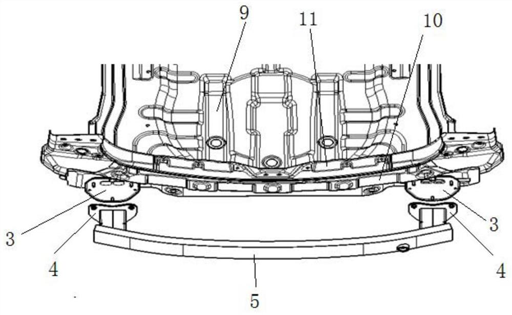
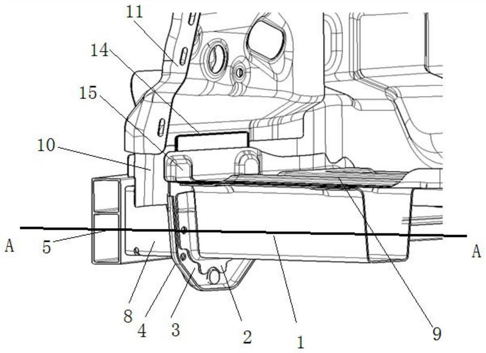
[0069]Figure 6 A schematic diagram of the post-collision beam connection structure of the present embodiment is shown;Figure 7 A sub-anti-collision beam connection structure exploded after the present embodiment is shown;Figure 8 showFigure 6 B-B profile;Figure 9A modification analysis of the post-collision beam connection structure of the present embodiment is shown.

[0070]Such asFigure 6 ,Figure 8 As shown, the rear collision beam connection structure includes: one side of the end plate reinforcing plate 2 is connected to the end of the rear beam 1, and the rear lever end plate 3 is disposed on the end plate reinforcing plate 2, and the outer plate 10 The outer surface of 10 is connected by welding, and then the collision beam 5 is connected to the rear collision beam mounting plate 4 through the suction cartridge 8, and the anti-collision beam mounting plate 4 is provided with a through hole, and the through hole corresponds to the suction cartridge 8. After the collision beam mou...


PUM


Abstract

The invention discloses an automobile rear anti-collision beam connecting structure and a rear anti-collision beam mounting method. The rear anti-collision beam connecting structure comprises an end plate reinforcing plate, a rear longitudinal beam end plate, and a rear anti-collision beam mounting plate; a pair of connecting plates are arranged on one surface of the end plate reinforcing plate, and one surface of the end plate reinforcing plate is connected to the end of a rear longitudinal beam; the pair of connecting plates are inserted into the rear longitudinal beam and are respectively welded on the inner walls of the two sides of the rear longitudinal beam; the rear longitudinal beam end plate is arranged on the end plate reinforcing plate and connected with the outer surface of therear wall outer plate in a welded mode. And the rear anti-collision beam is mounted on the rear longitudinal beam end plate through the rear anti-collision beam mounting plate. A sealing procedure isnot needed, the sealing cost is low, the potential quality hazard of untight sealing is eliminated, a boss does not need to be made on the rear floor to avoid a rear anti-collision beam connecting bolt, the forming procedure is reduced, the mold cost is reduced, the rear collision maintenance economy is improved, the weight and cost of an automobile are reduced, and therefore the market competitiveness of the automobile is improved.

Description

Technical field[0001]The present invention belongs to the field of automobile technology, and more particularly to the anti-collision beam connection structure after the car and the post-collision beam mounting method.Background technique[0002]After the collision beam is the important part of the vehicle body deformation, it contributes to the overall collision performance goal of the white car, and at the same time, in the rear collision test of the safety performance level, maintenance economy level, Post-collision beam has also played an important role, so there is a high strength requirement.[0003]The existing rear hemount mounting plate is connected by bolts, nuts, and rear beam end plates. In order to increase the stiffness and strength of the anti-collision beam, it is mainly used to increase the reinforcing plate. The traditional post-collision beam connection structure is likeFigure 1 ~ 4 As shown, the longitudinal beam end plate and the end plate reinforcing plate are firs...

Claims


Application Information

Patent Timeline
Patent Type & Authority Applications(China)
IPC IPC(8): B60R19/24
CPCB60R19/24
Inventor 熊本胜魏玉功刘志民
Owner BAIC MOTOR CORP LTD
Why Eureka
Try Eureka