
Micro light emitting diode chip and display panel

A technology of micro-light-emitting diodes and chips, which is applied in the direction of semiconductor devices, electrical components, circuits, etc., can solve the problems of poor display effect of micro-light-emitting diodes, achieve the effects of improving display effects, solving the difficulty of transfer, and avoiding optical crosstalk

Active Publication Date: 2021-03-30
CHENGDU VISTAR OPTEOLECTRONICS CO LTD
View PDF13 Cites 0 Cited by
  • Summary
  • Abstract
  • Description
  • Claims
  • Application Information

AI Technical Summary

Problems solved by technology

[0004] An embodiment of the present invention provides a micro light emitting diode chip and a display panel to solve the problem of poor display effect of the existing micro light emitting diodes

Method used


Image

  • Micro light emitting diode chip and display panel
  • Micro light emitting diode chip and display panel
  • Micro light emitting diode chip and display panel

Examples


Embodiment 1

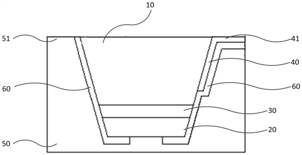
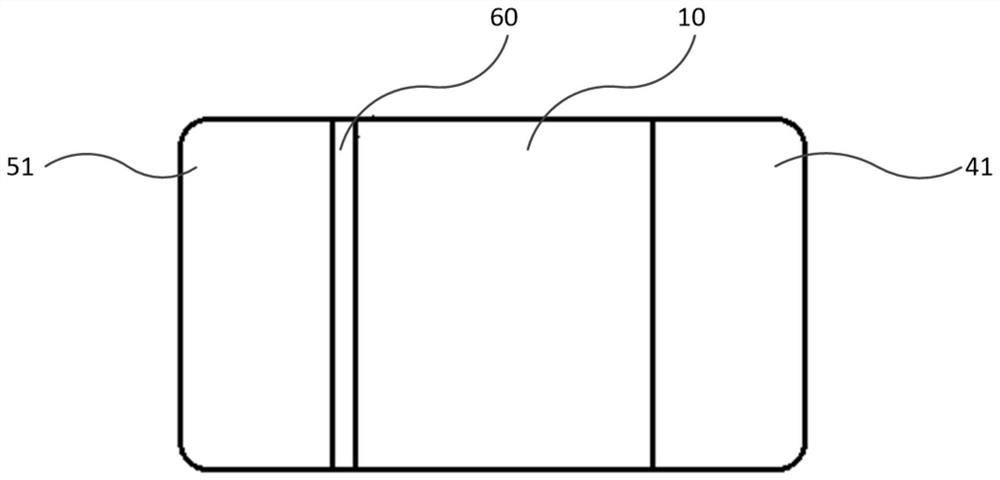
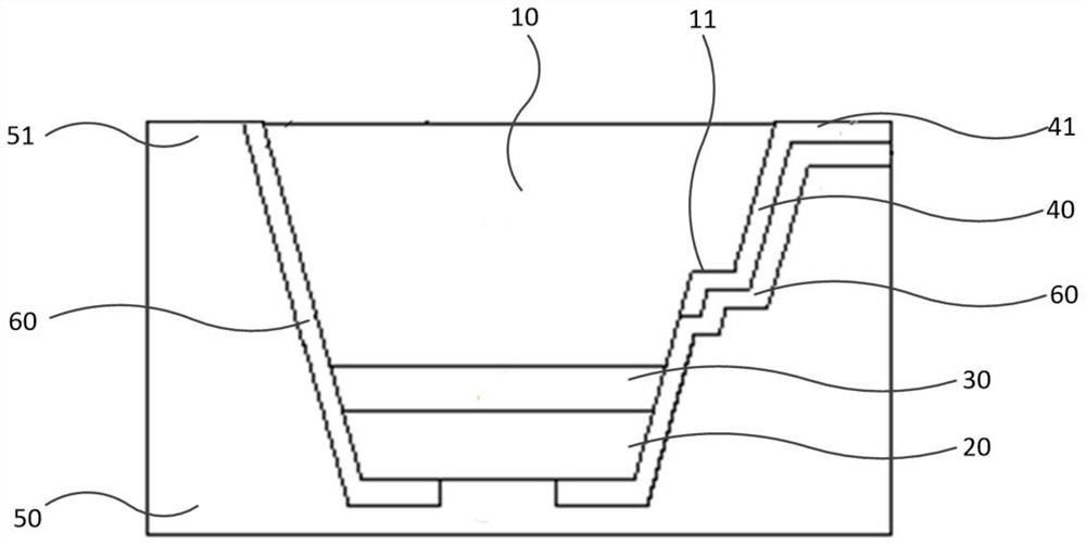
[0042] see Figure 1-Figure 3 , the micro light emitting diode chip provided by Embodiment 1 of the present invention includes a first type semiconductor layer 10, a light emitting layer 30, a second type semiconductor layer 20, a first type electrode layer 40, a second type electrode layer 50 and an insulating passivation layer 60 , wherein the first type semiconductor layer 10, the light emitting layer 30, and the second type semiconductor layer 20 are stacked in sequence; 10 ohm contact; the insulating passivation layer 60 covers part of the sidewall of the first type semiconductor layer 10, the sidewall and bottom surface of the first type electrode layer 40, the sidewall of the light emitting layer 30, the sidewall of the second type semiconductor layer 20 and the Part of the bottom surface; the second type electrode layer 50 covers the insulating passivation layer 60 , and the second type semiconductor layer 20 exposes part of the bottom surface of the insulating passiva...

Embodiment 2

[0059] The display panel provided by Embodiment 2 of the present invention includes the micro-LED chip provided in Embodiment 1 above, wherein the structure, function and implementation of the micro-LED chip can refer to the specific description in the above-mentioned embodiment, and will not be repeated here.

[0060] The display panel provided in this embodiment can be applied to any display device including a micro light-emitting diode chip and having a display function, such as a mobile phone, a tablet computer, a smart watch, an e-book, a navigator, a TV, a digital camera, and the like. The display panel provided in this embodiment also has the same advantages as the micro light-emitting diode chip provided in Embodiment 1, which will not be repeated here.


PUM

PropertyMeasurementUnit
angleaaaaaaaaaa

Abstract

The invention provides a micro light-emitting diode chip and a display panel, and the micro light-emitting diode chip comprises a first type semiconductor layer, a light-emitting layer, a second typesemiconductor layer, a first type electrode layer, a second type electrode layer, and an insulating passivation layer, wherein the first type semiconductor layer, the light-emitting layer and the second type semiconductor layer are stacked in sequence; the first type electrode layer is formed on the side wall of one side of the first type semiconductor layer; the insulating passivation layer covers part of the side wall of the first type semiconductor layer, the side wall and the bottom surface of the first type electrode layer, the side wall of the light emitting layer, the side wall and partof the bottom surface of the second type semiconductor layer; the second type electrode layer covers the insulating passivation layer, and the second type electrode layer is in ohmic contact with thepart, exposed out of the insulating passivation layer, of the second type semiconductor layer. According to the micro light emitting diode chip provided by the invention, the problems of high transfer difficulty and poor display effect of the existing micro light emitting diode chip are solved.

Description

technical field [0001] The invention relates to the field of display technology, in particular to a micro light emitting diode chip and a display panel. Background technique [0002] The micro-light-emitting diode (μLED) display panel is a display panel that integrates micro-light-emitting diode chips with a size of less than 100 microns on a substrate as display pixels to realize image display. A diode display panel is a self-luminous display panel. [0003] Due to the large side wall area of ​​the existing micro light emitting diode chip, there is an optical crosstalk problem caused by the light output from the side wall, and the optical cross talk problem will lead to a poor display effect of the display panel. Therefore, the existing micro light emitting diode chip has optical cross talk The problem of poor display effect caused. Contents of the invention [0004] Embodiments of the present invention provide a micro light emitting diode chip and a display panel to so...

Claims


Application Information

Patent Timeline
Patent Type & Authority Applications(China)
IPC IPC(8): H01L33/36H01L33/40H01L27/15
CPCH01L33/36H01L33/405H01L27/156H01L33/40H01L27/15H01L33/38H01L33/00H01L25/0753
Inventor 郭恩卿王程功盖翠丽
Owner CHENGDU VISTAR OPTEOLECTRONICS CO LTD
Learn More