
Device for automatically performing high-temperature detection by using self-weight of ceramics

An automatic, high-temperature technology, applied in the direction of ceramic molding machines, auxiliary molding equipment, manufacturing tools, etc., can solve the problems of increasing ceramics, energy waste, prolonging working time, etc., and achieve the effect of light weight

Inactive Publication Date: 2021-03-30
HUNAN UNIV OF TECH
View PDF0 Cites 0 Cited by
  • Summary
  • Abstract
  • Description
  • Claims
  • Application Information

AI Technical Summary

Problems solved by technology

[0004] Although traditional drying equipment can dry ceramics, it cannot be fixed, and the heating method of ceramics is fixed, so it cannot be dried evenly for different parts of ceramic parts; in addition, after drying , it needs to be cooled before it can be transferred to high-temperature-resistant testing equipment for heat-resistant testing. The transfer not only increases the risk of ceramic damage and prolongs the working time, but also requires reheating of the ceramic parts during the testing process, and testing The temperature of heating and drying is different, which will cause a waste of energy, so a device that uses the self-weight of ceramics to automatically detect high temperature came into being

Method used


Image

  • Device for automatically performing high-temperature detection by using self-weight of ceramics
  • Device for automatically performing high-temperature detection by using self-weight of ceramics
  • Device for automatically performing high-temperature detection by using self-weight of ceramics

Examples


Embodiment Construction

[0024] The following will clearly and completely describe the technical solutions in the embodiments of the present invention with reference to the accompanying drawings in the embodiments of the present invention. Obviously, the described embodiments are only some, not all, embodiments of the present invention. Based on the embodiments of the present invention, all other embodiments obtained by persons of ordinary skill in the art without making creative efforts belong to the protection scope of the present invention.

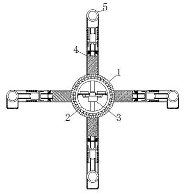
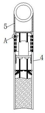
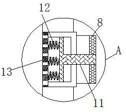
[0025] see Figure 1-7 , a device for automatically performing high-temperature detection by using the self-weight of ceramics, comprising a housing 1, a rotating shaft 2 is movably connected to the inside of the housing 1, and a heating element 3 is fixedly connected to the inside of the rotating shaft 2, and the heating element 3 includes a support plate 14, the support plate The surface of 14 is fixedly connected with the heating block 15, the surface of th...


PUM


Abstract

The invention relates to the technical field of ceramic high-temperature resistance detection, and discloses a device for automatically performing high-temperature detection by using the self-weight of ceramics. The device comprises a shell, wherein a rotating shaft is movably connected to the interior of the shell, a heating piece is fixedly connected to the interior of the rotating shaft, connecting rods are fixedly connected to the surface of the shell, placement boxes are movably connected to the ends, away from the shell, of the connecting rods, sliding rails are fixedly connected to theinteriors of the connecting rods, bearing plates are slidably connected to the surfaces of the sliding rails, and damping blocks are movably connected to the two sides of each bearing plate. Ceramic parts become lighter to fall on the surfaces of the bearing plates and then slowly slide to the surfaces of rotating plates; when the rotating shaft rotates by a circle again, moisture in ceramic partbodies is reduced again, the ceramic parts are lighter than before, the rotating plates can do the same motion as above, and the ceramic parts finally fall at the position closest to heating blocks; and the heat at the position is the same as the temperature for detecting the high-temperature resistance of the ceramic parts, so that the effect of performing high-temperature resistance detection without transfer is achieved.

Description

technical field [0001] The invention relates to the technical field of high-temperature resistance detection of ceramics, in particular to a device for automatically performing high-temperature detection by using the self-weight of ceramics. Background technique [0002] Ceramics are made of clay as the main raw material and various natural minerals through pulverization, mixing, molding and calcination, as well as various products; , glazing, kiln firing, painting, glaze color change and other processes. [0003] Ceramics after drying and molding need to be dried. Due to their unique durability, ceramics are very popular. Therefore, after drying, they need to be tested for high temperature resistance. After the testing is completed, they can be put on the market for sale. [0004] Although traditional drying equipment can dry ceramics, it cannot be fixed, and the heating method of ceramics is fixed, so it cannot be dried evenly for different parts of ceramic parts; in addi...

Claims


Application Information

Patent Timeline
IPC IPC(8): B28B11/24B28B17/00
CPCB28B11/243B28B17/00
Inventor 孙刚
Owner HUNAN UNIV OF TECH
Learn More