
A hot plate device for plasma dry degumming and its application method

A dry degumming and plasma technology, which is used in the manufacture of electrical components, circuits, semiconductor/solid-state devices, etc., to achieve the effect of increasing conduction efficiency, high dry degumming efficiency and wide application range.

Active Publication Date: 2022-02-11
ADVANCED MATERIALS TECH & ENG INC
View PDF6 Cites 0 Cited by
  • Summary
  • Abstract
  • Description
  • Claims
  • Application Information

AI Technical Summary

Problems solved by technology

[0004] The technical problem to be solved by the present invention is aiming at the three deficiencies proposed in the background technology of the heating plate in the existing plasma degumming machine. A hot plate device for dry deglue of a wafer and uniform surface temperature of the entire heating plate is used to solve the problems caused by the actual use of the heating plate in the existing ion degumming machine. problems or deficiencies

Method used


Image

  • A hot plate device for plasma dry degumming and its application method
  • A hot plate device for plasma dry degumming and its application method
  • A hot plate device for plasma dry degumming and its application method

Examples


Embodiment 1

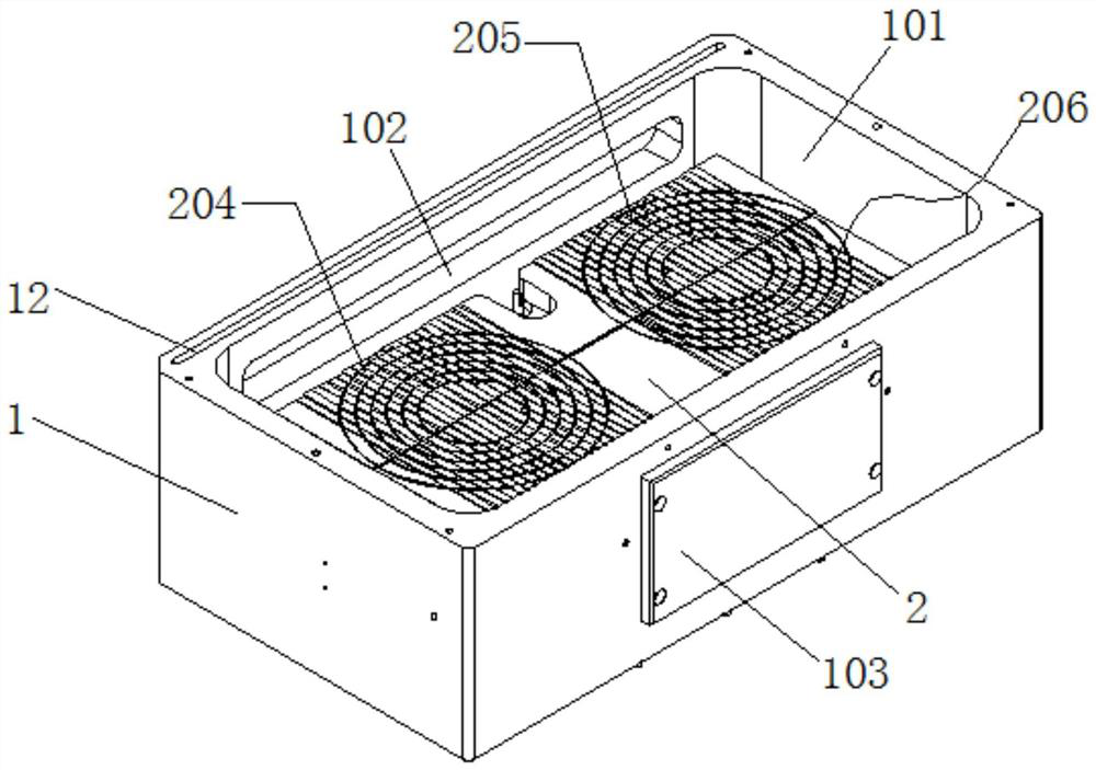
[0044] The present embodiment 1 discloses a hot plate device for degumming by plasma dry method. figure 1 , one of its main bodies includes a process cavity 1 , the process cavity 1 is in the shape of a rectangular parallelepiped as a whole, and a heating groove 101 is opened on the upper surface of the process cavity 1 . At the same time, a wafer extraction port 102 is also opened on the rear side of the process chamber 1, and a brand-name plate 103 is provided on the front side of the process chamber 1; The wafer is taken out, and the setting of the name plate 103 can surface the relevant information of the whole device.

[0045] Reference attached figure 1 , a heating plate body 2 is fixedly arranged in the heating groove 101. When specifically set, the heating plate body 2 is made of aluminum whose surface has been anodized, and the heating plate body 2 made of anodized aluminum can The heat is efficiently transferred to the surface of the product, and the uniformity of ...

Embodiment 2

[0051] This embodiment 2 discloses a hot plate device based on the improved dual-station plasma dry method based on the embodiment 1. It will be described in detail below with reference to the accompanying drawings.

[0052] This embodiment 2 discloses a hot plate device for double-station plasma dry degumming. figure 1 , one of its main bodies includes a process cavity 1 , the process cavity 1 is in the shape of a rectangular parallelepiped as a whole, and a heating groove 101 is opened on the upper surface of the process cavity 1 . At the same time, a wafer extraction port 102 is also opened on the rear side of the process chamber 1, and a brand-name plate 103 is provided on the front side of the process chamber 1; The wafer is taken out, and the setting of the name plate 103 can surface the relevant information of the whole device.

[0053] Reference attached figure 1 , a heating plate body 2 is fixedly arranged in the heating groove 101. When specifically set, the heati...


PUM


Abstract

The invention relates to the technical field of plasma degumming machines, and specifically discloses a hot plate device for plasma dry degumming; it includes a process cavity, a heating plate is fixedly arranged in the process cavity, and T is provided on the front and rear sides of the heating plate. A resistance heating rod penetration groove is opened in the heating disc body inside each T-shaped insertion slot; a number of first threaded holes are evenly opened on the side of the heating disc body located above and below the T-shaped insertion slot, and the T-shaped insertion slot A T-shaped resistance rod fixing block matching the T-shaped insertion groove is arranged in the groove, and the upper and lower sides of the outer end of the T-shaped resistance rod fixing block are provided with first through holes corresponding to each first threaded hole. A through hole is provided with a fixing bolt screwed to the first threaded hole; the heater in the heating plate disclosed in the present invention is fixed with a detachable design, which can be replaced separately after damage, greatly reducing maintenance and production costs, and at the same time The double-station design can meet the process temperature requirements of two product sheets at the same time.

Description

technical field [0001] The invention relates to the technical field of plasma degumming machines, and specifically discloses a hot plate device for degumming by a plasma dry method and a use method thereof. Background technique [0002] The manufacturing process of semiconductor devices includes thin film deposition, exposure, etching, photoresist removal, and wet cleaning, wherein the photoresist removal is performed on a plasma stripper. At present, the heating plate of the ion degumming machine is divided into flat type and groove type. Among them, the flat heating plate is in direct contact with the backside of the wafer, which causes the wafer to be heated too quickly, resulting in poor uniformity of the etched photoresist, while the grooved heating plate heats the surface of the wafer more Evenly, its heating effect is better. [0003] The utility model with the patent number CN211017022U discloses a heating plate of a plasma degumming machine, which includes a plate...

Claims


Application Information

Patent Timeline
Patent Type & Authority Patents(China)
IPC IPC(8): H01L21/67
CPCH01L21/67011
Inventor 廖海涛
Owner ADVANCED MATERIALS TECH & ENG INC
Learn More