
Efficient air supply outlet structure based on energy conservation and environmental protection

An energy-saving, environmentally friendly and air-supply technology, which is applied to the components of the pumping device for elastic fluids, pipeline arrangement, non-variable-capacity pumps, etc. and other problems, to achieve the effect of reducing dust and self-locking

Active Publication Date: 2021-03-26
宁夏海美祥建设工程有限公司 +1
View PDF12 Cites 0 Cited by
  • Summary
  • Abstract
  • Description
  • Claims
  • Application Information

AI Technical Summary

Problems solved by technology

[0007] The purpose of the present invention is to provide a high-efficiency air supply structure based on energy saving and environmental protection, so as to solve the problem that the currently used air supply structure proposed in the above background technology does not have the function of quickly and automatically opening or closing the natural air outlet and using other components to assist air suction. It has the function of quickly and automatically starting and running the mechanical air supply, and the problem that the mechanical air supply outlet cannot be closed after the mechanical air supply is stopped

Method used


Image

  • Efficient air supply outlet structure based on energy conservation and environmental protection
  • Efficient air supply outlet structure based on energy conservation and environmental protection
  • Efficient air supply outlet structure based on energy conservation and environmental protection

Examples


Embodiment Construction

[0031] The following will clearly and completely describe the technical solutions in the embodiments of the present invention with reference to the accompanying drawings in the embodiments of the present invention. Obviously, the described embodiments are only some, not all, embodiments of the present invention.

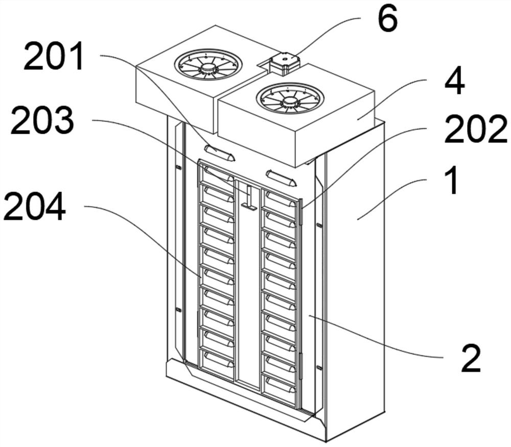
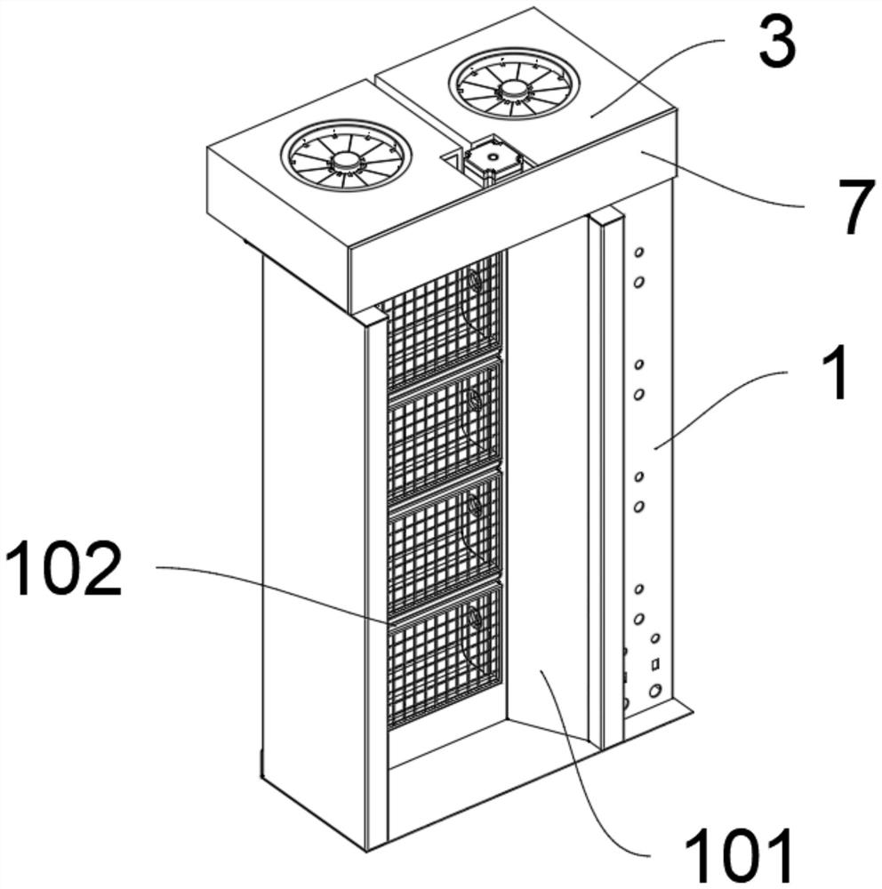
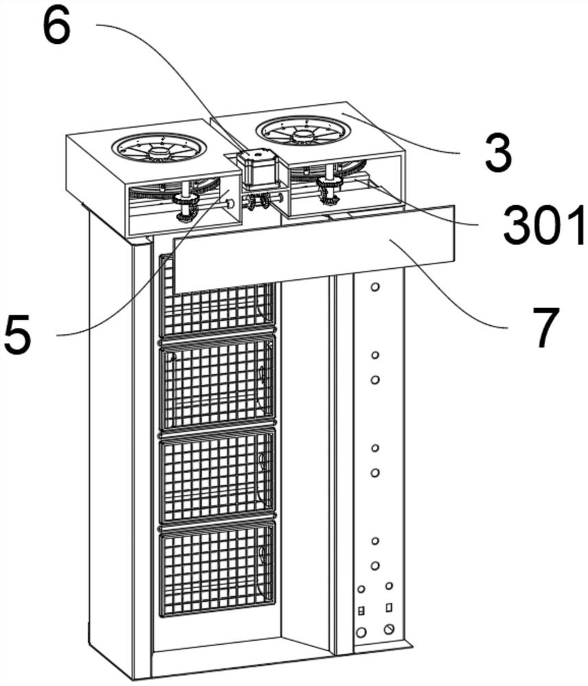
[0032] see Figure 1 to Figure 8, an embodiment provided by the present invention: a high-efficiency air supply structure based on energy saving and environmental protection, including a main channel 1; the main channel 1 also includes an air outlet channel 101, an exhaust net 102, and a top plate 103; the rear side of the main channel 1 An air outlet channel 101 is provided in one piece; the rear side of the air outlet channel 101 is fixed with an exhaust net 102 by bolts; the top of the main channel 1 is fixed with a top plate 103, and two sets of square holes are opened in the middle of the top plate 103, and the square holes The tops of the tops are all fixed wit...


PUM


Abstract

The invention discloses an efficient air supply outlet structure based on energy conservation and environmental protection, relates to the technical field of environmental protection application, andsolves the problem that an air supply outlet structure used at present does not have the function of assisting air suction by utilizing other elements after a natural air opening is rapidly and automatically opened or closed. The efficient air supply outlet structure based on the energy conservation and environmental protection comprises a main channel; the main channel further comprises an air outlet channel, an exhaust net and a top plate; the air outlet channel is integrally arranged at the rear side of the main channel; the exhaust net is fixedly arranged on the rear side of the air outletchannel through bolts, a sealing function is provided for the air inlet by arranging a sealing row, natural ventilation can be kept through the air inlet, a fan ring shell can be connected with external natural air, and it is guaranteed that indoor airflow confusion cannot be caused in the mechanical air supply process; and when wind power conveying needs to be accelerated, a grid structure of the sealing row is attached to the bottom of the air inlet, the bottom of the air inlet is sealed, and indoor natural wind is prevented from flowing.

Description

technical field [0001] The invention relates to the technical field of environmental protection applications, in particular to an energy-saving and environment-friendly high-efficiency air supply port structure. Background technique [0002] The air supply port refers to the nozzle that transports air from the center of the air conditioning duct to the room. The shell of the air outlet is made of high-quality cold-rolled steel plate, with electrostatic spraying on the surface, including static pressure box, high-efficiency filter, and diffuser plate. It can be used as a terminal high-efficiency filter device in clean ceilings and other places during reconstruction and new construction of clean rooms at all levels. It has the advantages of less investment and simple construction. [0003] After searching, for example, the patent No. CN208139541U discloses an energy-saving and environmentally friendly high-efficiency air supply structure, including a blower box and a connecti...

Claims


Application Information

Patent Timeline
IPC IPC(8): F24F13/06F04D29/40
CPCF04D29/403F24F13/06
Inventor 李丹
Owner 宁夏海美祥建设工程有限公司
Learn More