
Rubber-tired train

A technology for trains and rubber wheels, applied to motor vehicles, vehicle parts, steering mechanisms, etc., can solve the problems of poor traction effect of traction drive devices and achieve good traction effects

Active Publication Date: 2021-03-26
CRRC NANJING PUZHEN CO LTD
View PDF7 Cites 1 Cited by
  • Summary
  • Abstract
  • Description
  • Claims
  • Application Information

AI Technical Summary

Problems solved by technology

[0004] The embodiment of the present application provides a rubber-tired train, which is mainly used to solve the problem of poor traction effect of the traction drive device in the related art

Method used


Image

  • Rubber-tired train
  • Rubber-tired train
  • Rubber-tired train

Examples


Embodiment 1

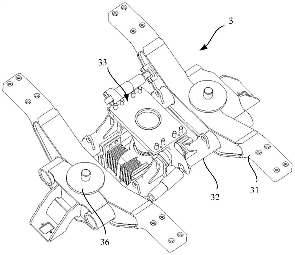
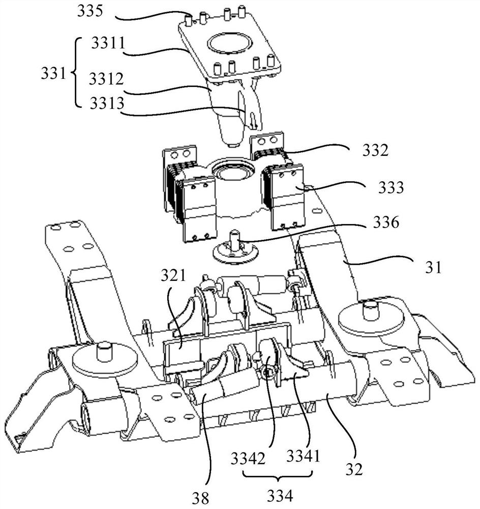
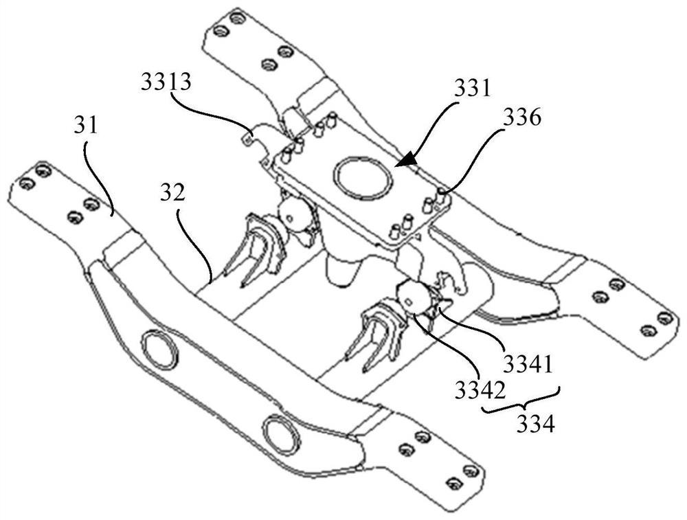
[0065] figure 1 Shown in is a schematic structural diagram of a motor car bogie provided by an embodiment of the present application; figure 2 Shown in is a schematic diagram of the connection structure between the motor vehicle traction device and the frame provided by an embodiment of the application; please refer to Figure 1-Figure 2 .

[0066] This embodiment provides a motor car bogie 3, which includes a frame, a traction center pin 331 and a motor car traction device 33; wherein, the frame is the installation basis for the motor car traction device 33 and the traction center pin 331, and the frame includes two side beams 31 and Two crossbeams 32 and two sidebeams 31 extend along the length direction of the vehicle body. The two sidebeams 31 are parallel and oppositely arranged, and are respectively located at the edge of the frame. Two crossbeams 32 extend along the width direction of the vehicle body. The two crossbeams 32 can be arranged parallel and opposite to ea...

Embodiment 2

[0114] This embodiment provides a rubber-tyred train, which includes a first car body and a second car body that are oppositely arranged. The side of the first car body away from the second car body is provided with the motor car bogie as described in the first embodiment above. The first car body and the second car body are connected through a trailer bogie. Obviously, in this embodiment, the first car body is a motor car body, and the second car body can be an intermediate car body or a motor car body.

[0115] Since the rubber-tired train of this embodiment is provided with the motor car bogie described in the first embodiment above, it can simultaneously control the steering of the first motor wheel pair and the second motor wheel pair through a set of motor car steering drive device, ensuring that it is consistent with the steering of the motor car. The flexibility of the steering of the car body connected to the frame.

[0116] further, Figure 11 Shown in is the struc...


PUM


Abstract

The embodiment provides a rubber-tired train which comprises at least two connected train bodies, at least one train body is provided with a bullet train traction driving device, the bullet train traction driving device comprises a traction motor, a driving axle and a transmission shaft, and an output shaft of the traction motor is used for outputting traction force; the input end of the drive axle is connected with the output shaft of the traction motor; the two ends of the transmission shaft are fixedly connected with the output end of the traction motor and the input end of the drive axle respectively, the transmission shaft comprises a first transmission part, a second transmission part and a third transmission part, the first end of the first transmission part is fixedly connected with the output shaft of the traction motor, and the second end of the first transmission part is hinged to the first end of the second transmission part. The second end of the second transmission part is hinged to the first end of the third transmission part, and the second end of the third transmission part is fixedly connected with the input end of the drive axle. The transmission shaft in the rubber-tired train can adapt to the height difference generated between the motor and the drive axle due to various working conditions and transmit torque normally, and the traction effect is good.

Description

technical field [0001] The present application relates to vehicle manufacturing technology, in particular to a rubber-tyred train. Background technique [0002] With the development of urban traffic construction, articulated trains (such as traditional low-floor trams, traditional trolleybuses, urban BRT trains, etc.) are gradually put into use to relieve road traffic pressure. An articulated train is a wheeled train composed of two or more carriages connected together by a hinge device. The articulated train changes its forward direction by the guidance of the hinge device between the carriages. [0003] In the scheme of the related art, the traction driving device is the power source of the articulated train, which is used to drive the whole train forward; The axle transmits the power output by the traction motor to the drive axle. However, during the operation of the train, there may be a height difference between the traction motor and the drive axle, and at this time,...

Claims


Application Information

Patent Timeline
Patent Type & Authority Applications(China)
IPC IPC(8): B60K1/00B60K17/22B62D7/04B62D7/20B62D47/02
CPCB60K1/00B60K17/22B62D7/04B62D7/20B62D47/02
Inventor 冯遵委金雄峰周丙南杨红伟尤君张迪
Owner CRRC NANJING PUZHEN CO LTD
Learn More