Spraying device for glazing perforated ceramic
A spraying device and a technology for ceramics, applied in the field of ceramics processing, can solve problems such as difficulty in spraying and glazing
- Summary
- Abstract
- Description
- Claims
- Application Information
AI Technical Summary
Problems solved by technology
Method used
Image
Examples
Embodiment 1
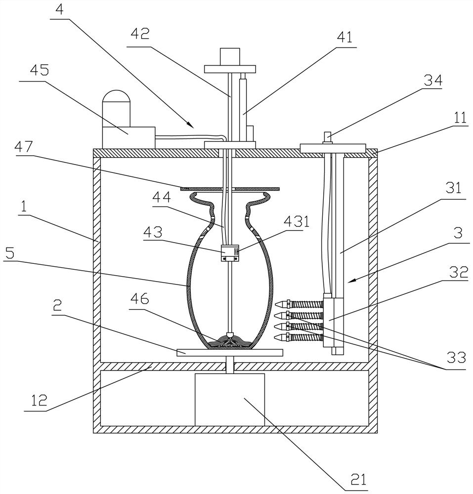
[0023] refer to figure 1 , a spraying device for glazed ceramics with holes, comprising a spraying box 1 and a workbench 2, the workbench 2 can be horizontally rotatably arranged in the spraying box 1, and one side of the spraying box 1 is provided with a The ceramic with holes 5 on the top is sprayed with a spraying mechanism 3 for glazing, and the spray box 1 is also provided with an air source mechanism 4 that can extend into the ceramic with holes 5. In the porous ceramic 5 or the air in the porous ceramic 5 is blown out of the air flow outside the porous ceramic 5.
[0024] refer to figure 1 , more specifically, the upper end of the spray box 1 is provided with a cover 11 with an installation port, the inside of the spray box 1 is provided with a partition 12, and the above partition 12 is arranged with the workbench 2, and the spray box 1 is placed on the top of the partition 12. A driving motor 21 is fixedly arranged below, and the output shaft of the driving motor 21...
Embodiment 2
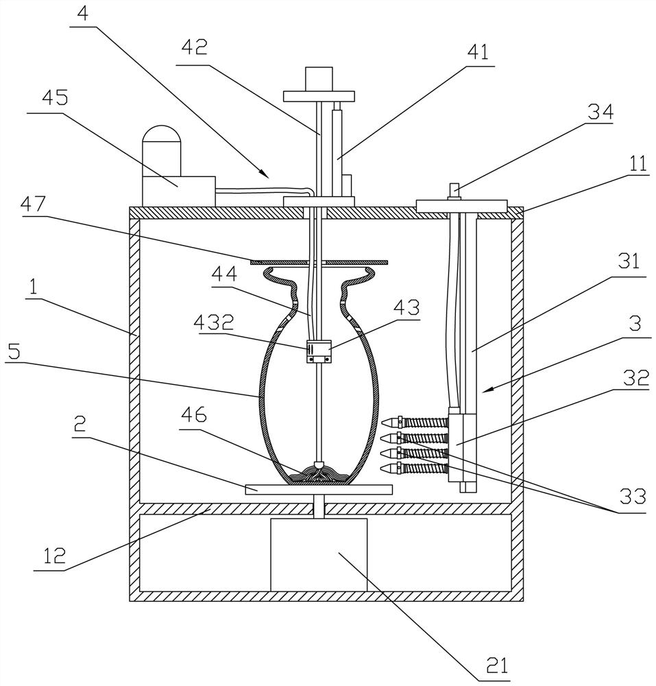
[0030] refer to figure 2 , the structure of this embodiment is basically the same as that of Embodiment 1, and will not be repeated here. The difference is that: the sliding seat of the first electric linear guide rail 42 is provided with an air nozzle 43 for sucking air, and the air nozzle 43 faces away from the Or face the side of the spraying mechanism 3 and be provided with several air suction ports 432 for air suction. When the wind force is sufficient, the air suction ports 432 arranged on the back can effectively prevent the glaze water from being sucked into the air suction ports 432. When the wind power is insufficient, then use facing spraying Institution 3. When the spraying mechanism 3 is spraying the holes on the ceramic 5 with holes, the tuyere 43 is driven by the first electric linear guide rail 42 to move to the corresponding position of the hole in the ceramic 5 with holes, and under the action of the air pump 45 The draft makes negative pressure be formed i...
Embodiment 3
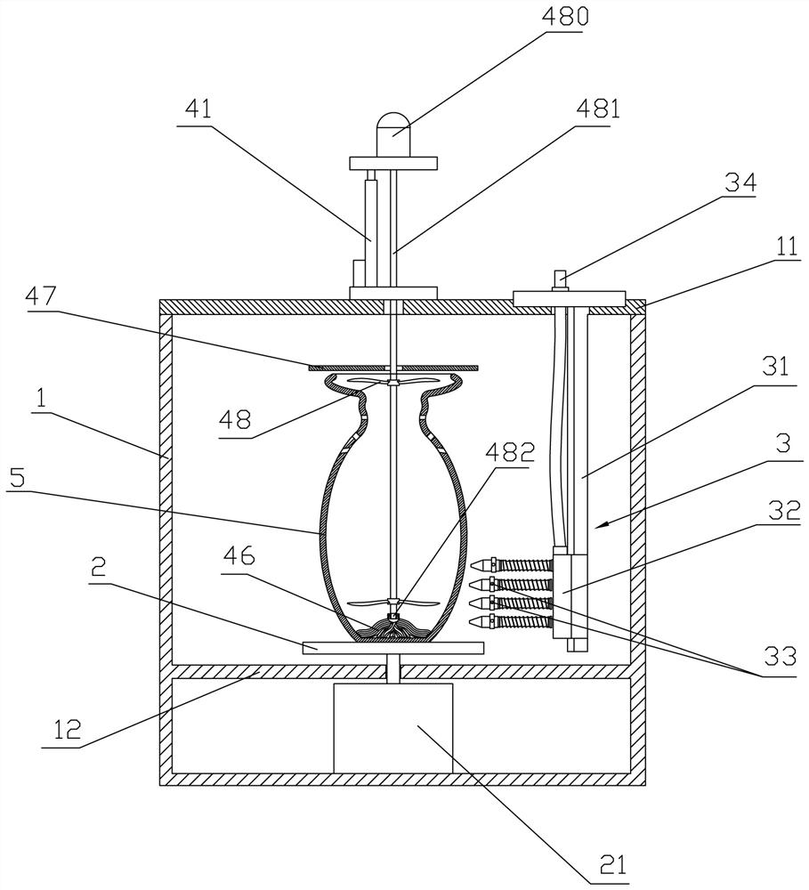
[0032] refer to image 3, the structure of this embodiment is basically the same as that of Embodiment 1, and will not be repeated here. The difference is that: the wind source mechanism 4 includes a pole that can extend into the ceramic 5 with holes, and the pole is provided with holes for disturbing The air in the ceramic 5 forms a rotating vane 48 of turbulent flow. The rotating vane 48 is made of a flexible material and is two, which are respectively distributed above and below in the ceramic 5 with holes, and fan the wind downwards and upwards respectively, i.e. two Two rotating fan blades 48 fan the wind in opposite directions, forming air turbulence. The strut is a rotating shaft 481 of a rotating motor 480 , and the rotating blade 48 is fixed on the rotating shaft 481 . The end of the rotating shaft 481 is connected with the absorbent cloth 46 through a bearing cover 482 . The turbulent flow of air formed by the rotating blades 48 in the ceramic 5 with holes in this ...
PUM
 Abstract
Description
Claims
Application Information
 - R&D Engineer
- R&D Manager
- IP Professional
- Industry Leading Data Capabilities
- Powerful AI technology
- Patent DNA Extraction
Browse by: Latest US Patents, China's latest patents, Technical Efficacy Thesaurus, Application Domain, Technology Topic, Popular Technical Reports.
© 2024 PatSnap. All rights reserved.Legal|Privacy policy|Modern Slavery Act Transparency Statement|Sitemap|About US| Contact US: help@patsnap.com


