SCR low-temperature denitration device

A low-temperature denitrification and catalyst technology, which is applied to the separation of dispersed particles, chemical instruments and methods, and separation methods, can solve the problems of catalyst agglomeration deactivation, low catalytic efficiency, and insufficient cooling effect of adsorption to extend the reaction time. , the effect of improving the catalytic efficiency

Active Publication Date: 2021-03-26
YANCHENG LANFENG ENVIRONMENTAL ENG TECH
View PDF6 Cites 1 Cited by
  • Summary
  • Abstract
  • Description
  • Claims
  • Application Information

AI Technical Summary

Problems solved by technology

[0004] The purpose of the present invention is to provide a SCR low-temperature denitration device to solve the problems of easy agglomeration and deactivation of the catalyst in the denitration reactor, the adsorption of the catalyst to the flue gas, insufficient cooling effect, and low catalytic efficiency.

Method used


Image

  • SCR low-temperature denitration device
  • SCR low-temperature denitration device
  • SCR low-temperature denitration device

Examples


Embodiment 1

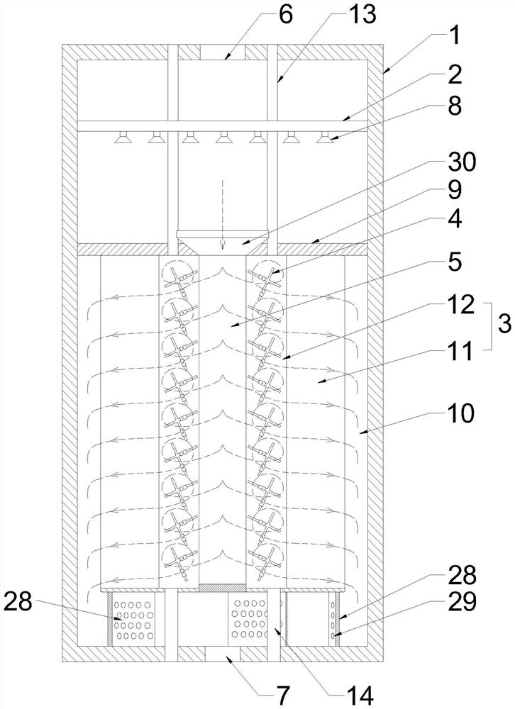
[0031] Such as Figure 1 to 4 As shown, a SCR low temperature denitration apparatus includes a reactor housing 1, a spray gate 2, a catalyst reservoir 3, a tip fixture 4, and an inner tube 5. The top of the reactor housing 1 has a flue gas inlet 6, and the bottom is provided with a flue gas outlet 7, and the desulfurization is low-temperature smoke (170-250 ° C) is injected into the reactor housing 1 in the reactor housing 1 by the flue gas inlet 6.

[0032] The spray head 8 of the via the ammonia line is mounted on the spray gate 2, and the sprayed head 8 is sprayed with a gasification, which contains NO. X Flue gas denitration, the primary product after the reaction is n 2 Ho 2 O, remove the reactor housing 1 by the flue gas outlet 7 after removing the ammonium salt, dust such as a catalyst reservoir.

[0033] The catalyst cartridge 3 is fixed to the reactor housing 1 and below the spray ammonagner 2, and the top portion of the catalyst reservoir 3 is fixedly mounted, and the ba...

Embodiment 2

[0049] Such as Figure 5 As shown, the difference from the present embodiment and the first embodiment is that the base structure is different. The base of the present embodiment includes a plurality of arcuate guiding plates 32, and the guide plate 32 is arranged along the screw trajectory, and the spiral trajectory The airflow flowing between the adjacent fluid plates 32, the air flow flowing out of the flue gas overflow passage 10 is quickly flowing into the flue gas outlet 7 along the spiral trajectory after the engaging air gap 33, and then pumped into the chimney by the air blower. Among them, a plurality of vent holes 29 are also provided on the outermost circular fluid plate, which facilitates the quick flow of 10 in the flue gas overflow passage to enter the spiral trajectory of the vent hole 29 into the inner ring.


PUM


Abstract

The invention provides an SCR low-temperature denitration device, and the device comprises: a reactor shell, which is equipped with a flue gas inlet and a flue gas outlet; an ammonia spraying grid, which is provided with spraying heads; and a catalyst storage cylinder, wherein a flue gas overflow channel is reserved between the catalyst storage cylinder and the inner side wall of the reactor shelland is communicated with the flue gas outlet; the catalyst storage cylinder comprises a catalyst outer cylinder and a catalyst inner cylinder located in the catalyst outer cylinder, a material turning piece is installed in the catalyst inner cylinder, the material turning piece is provided with a fork-shaped piece capable of rotating in a reciprocating mode, and the fork-shaped piece stirs catalyst particles in the catalyst inner cylinder when rotating; a reactor inner pipe is located in the middle of the catalyst outer cylinder, the catalyst inner cylinder abuts against the reactor inner pipe, an air inlet is formed in the top of the reactor inner pipe, the bottom of the reactor inner pipe is of a sealed structure, and flue gas entering the reactor inner pipe from the air inlet passes through the catalyst inner cylinder and the catalyst outer cylinder in the radial direction and then enters the flue gas overflow channel. The problems that the catalyst in a denitration reactor is easyto cake and inactivate and the catalytic efficiency is low can be solved.

Description

Technical field [0001] The present invention belongs to the technical field of environmental protection equipment, and more particularly to a SCR low temperature denitration device. Background technique [0002] Pollutants in the smoke in the migrant of the fire, sulfur dioxide, nitrogen oxides, etc., the flue gas control path can be treated first, then enter the high-temperature bag dust, then enter the SCR reactor denitration, and finally discharged from the air blower. In the chimney. [0003] Since the flue gas after desulfurization still contains a small amount of SO X It has a catalyst to be catalyst or inactivated by a catalyst that is adsorbed to the reactor after reacting the ammonia gas in the SCR reactor, and the ammonium salt is easily catalyst or deactivated due to increased viscosity, and shorten the operating cycle of the catalyst. In addition, since the catalyst bed is usually a fixed bed, the contact area of ​​the flue gas and the catalyst is small in the premise...

Claims


Application Information

Patent Timeline
Patent Type & Authority Applications(China)
IPC IPC(8): B01D53/90B01D53/88B01D53/56
CPCB01D53/90B01D53/8631B01D53/88
Inventor 范兰张锐万加兵王苏林
Owner YANCHENG LANFENG ENVIRONMENTAL ENG TECH
Why Eureka
Try Eureka