
Stimulation coil positioning device

A positioning device and coil technology, applied in the field of medical equipment, can solve problems such as poor positioning effect, achieve good performance, ensure reliability, and improve the effect of treatment

Active Publication Date: 2021-03-26
四川君健万峰医疗器械有限责任公司
View PDF20 Cites 0 Cited by
  • Summary
  • Abstract
  • Description
  • Claims
  • Application Information

AI Technical Summary

Problems solved by technology

[0005] The purpose of the present invention is to provide a stimulating coil positioning device to solve the problem of poor positioning effect in the use of existing stimulating coils

Method used


Image

  • Stimulation coil positioning device
  • Stimulation coil positioning device
  • Stimulation coil positioning device

Examples


Embodiment 1

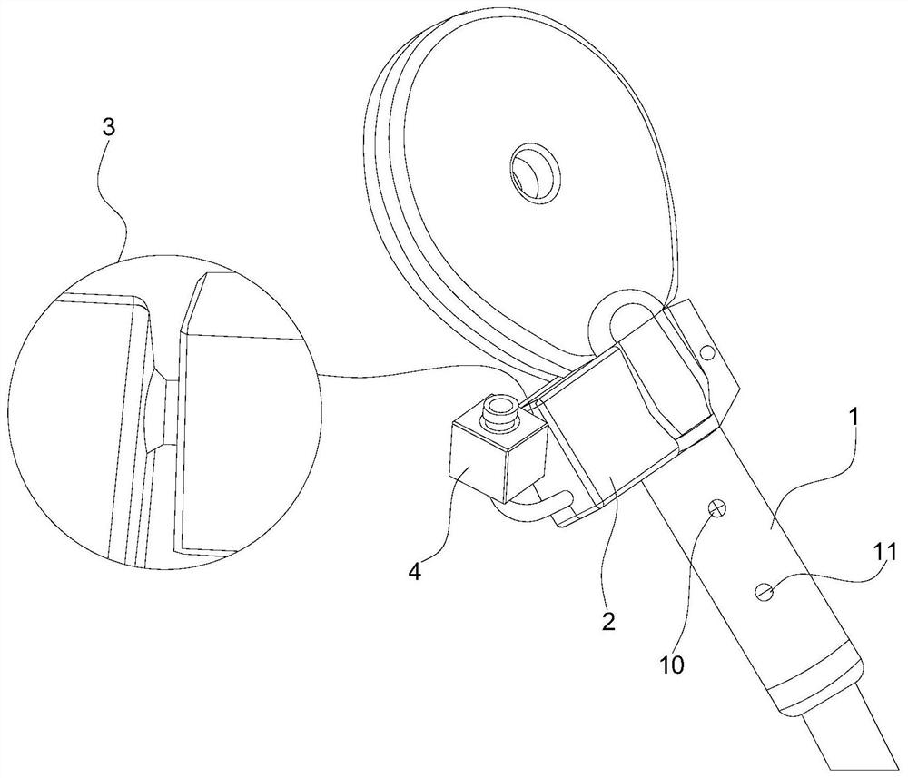
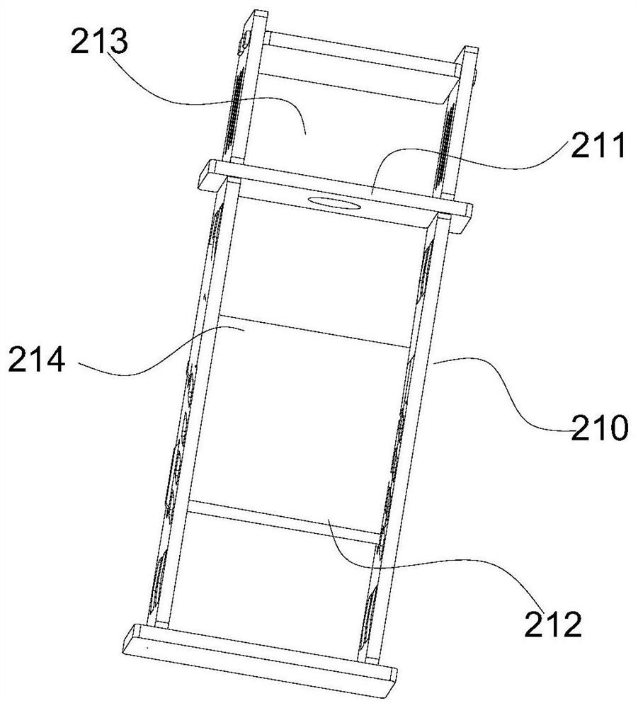
[0042] Embodiment one: if Figure 4 As shown, the adjustment mechanism 3 includes a driving motor 30 arranged in the side installation area 213, a driving gear 31 connected to the output end of the driving motor 30, and a driven gear 32 meshed with the driving gear 31. The driven gear 32 cooperates There is a support shaft 33 , which is fitted on the side wall of the frame body 210 through a bearing, and the end of the support shaft 33 away from the driven gear 32 penetrates the frame body 210 and is connected with the detection assembly 4 . The driving motor 30 provides the driving force, and the driving gear 31 and the driven gear 32 serve as the transmission part to transmit the rotational torque to the detection assembly 4, thereby realizing the adjustment of the rotation angle of the detection assembly 4, which is convenient and quick to operate and reliable to adjust. Specifically, when in use, the driving motor 30 is turned on to drive the driving gear 31 to rotate, and...

Embodiment 2

[0044] Embodiment two: if Figure 5 As shown, the adjustment mechanism includes a universal joint arranged on the outer wall of the positioning frame and a plastic pipe connected to the universal joint, and the detection assembly is connected to the end of the plastic pipe away from the universal joint. The rotation adjustment of the plastic pipe fitting and the detection assembly at any angle is realized through the universal joint, and the position of the detection assembly is adjusted according to the use needs through the plastic deformation function of the plastic pipe fitting, which is convenient and reliable, and the manual adjustment is reliably realized.

[0045] like Image 6 As shown, the detection assembly 4 includes a housing 40 and a camera 41 disposed in the housing 40 , the lens of the camera 41 extends out of the housing 40 , and the housing 40 is mated with the support shaft 33 . The camera 41 is used to capture the positioning point, and sends an instructio...


PUM


Abstract

The invention discloses a stimulation coil positioning device. The device comprises a positioning rod, a positioning mechanism arranged at the end of the positioning rod in a sleeving mode and a detection assembly connected to the positioning mechanism through an adjusting mechanism and used for detecting a positioning point, the positioning mechanism comprises a positioning sleeve arranged on thepositioning rod in a sleeving mode and moving in the axial direction of the positioning rod and a positioning frame connected to the end of the positioning sleeve and connected with the positioning sleeve into an integrated structure, a fastening plate of an opening structure is arranged at the end, away from the positioning frame, of the positioning sleeve, and a fastener used for adjusting thesize of an opening is arranged on the fastening plate. The device is reliable in structure, good in use performance, accurate in positioning and convenient to operate, a stimulation coil is installedon the positioning rod to form a reliable stimulation coil supporting structure, accurate identification of the positioning point of a head of a patient is achieved through reliable positioning of thepositioning mechanism, angle adjustment of a detection mechanism by the adjusting mechanism and accurate detection of the detection mechanism, therefore, the stimulation coil is accurately positionedto a treatment part, and the purpose of accurate treatment is achieved.

Description

technical field [0001] The invention relates to the technical field of medical devices, in particular to a stimulating coil positioning device. Background technique [0002] In the field of transcranial magnetic stimulation, the "magnetic field stimulator" directly approaches and acts on the human body. The stimulating coil is the key component in the magnetic field stimulator. Its function is to use a strong pulse current to generate a strong alternating magnetic field, thereby Inductive electric field is generated in human tissue, which induces nerve reaction points, stimulates local nerve cell depolarization and causes nerve action potential to produce excitatory or inhibitory effects, thereby producing a series of physiological and biochemical reactions to achieve detection or treatment functions. [0003] The impact of its technical requirements on the treatment effect is mainly in three aspects: 1. Focusing effect and accurate positioning. 2. The depth of stimulation ...

Claims


Application Information

Patent Timeline
Patent Type & Authority Applications(China)
IPC IPC(8): A61N2/02
CPCA61N2/006A61N2/02
Inventor 关灯景
Owner 四川君健万峰医疗器械有限责任公司
Learn More