Energy consumption connecting joint of shear wall

A technology for connecting nodes and shear walls, applied in the direction of walls, building components, building structures, etc., can solve problems such as damage, and achieve the effect of increasing support points, not easy to fail, and increasing friction.

Pending Publication Date: 2021-03-23
TONGJI UNIV ARCHITECTURAL DESIGN INST GRP CO LTD
View PDF1 Cites 2 Cited by
  • Summary
  • Abstract
  • Description
  • Claims
  • Application Information

AI Technical Summary

Problems solved by technology

[0005] Although the patent improves the ductility of the shear wall, the patent pre-embeds high-strength steel in the shear wall and relies on the plastic yield of the high-strength steel to dissipate energy, which may still occur under large cumulative plastic deformation destroy

Method used


Image

  • Energy consumption connecting joint of shear wall
  • Energy consumption connecting joint of shear wall
  • Energy consumption connecting joint of shear wall

Examples


Embodiment 1

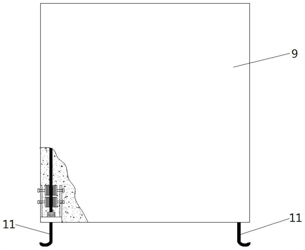
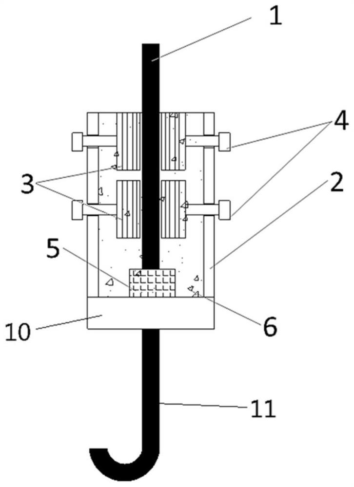
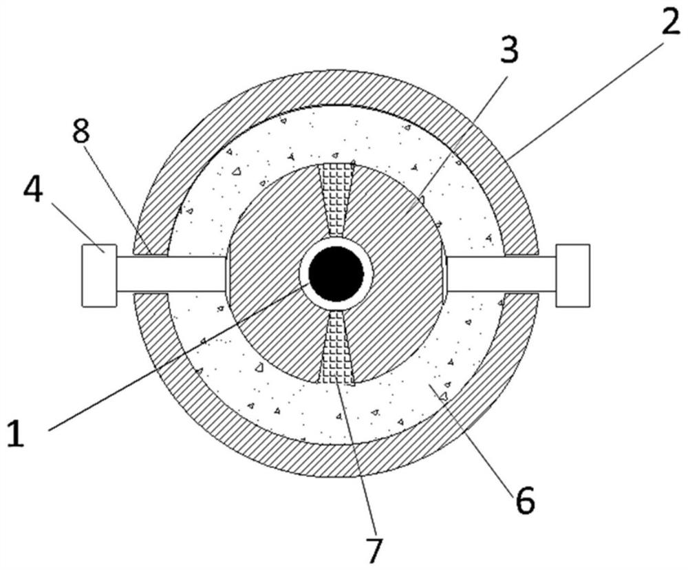
[0034] An energy-dissipating connecting node of a shear wall, used to connect the shear wall 9 and the connected parts, such as figure 1 , figure 2 and image 3 , comprising a first connection module and a second connection module pre-embedded in the corner of the shear wall 9 and the connected parts respectively, the first connection module and the second connection module are connected, the first connection module includes a steel bar 1 and a casing 2, The steel bar 1 is inserted into the casing 2, and two frictional energy dissipation units are arranged between the steel bar 1 and the casing 2, and the two frictional energy dissipation units are arranged at intervals along the axial direction of the casing 2, and each frictional energy dissipation unit includes two friction plates 3 and the corresponding two pre-tightening bolts 4, the two friction plates 3 surround and cling to the side wall of the steel bar 1, the sleeve 2 has a threaded hole 8, the end of the pre-tight...

Embodiment 2

[0048] Such as Figure 5 , the structure of the second connection module is the same as that of the first connection module in this embodiment, and they are arranged symmetrically. 5 Integrated design, simple structure, further improves the ductility of energy-dissipating connection nodes. Others are the same as in Example 1.

[0049] Embodiment 1 and Embodiment 2 propose an energy-dissipative connection node of a shear wall, which applies friction to the steel bar 1 through the casing 2, the pre-tightening bolt 4 and the friction plate 3. When the steel bar 1 is axially loaded along the casing 2 Relative sliding occurs when the force is greater than the frictional force, so as to prevent the steel bar 1 from yielding due to excessive force. It has good ductility, strong energy dissipation capacity, and is not easy to be damaged. At the same time, it is easy to disassemble and assemble, and is convenient for repair and replacement of damaged corners.


PUM


Abstract

The invention relates to an energy consumption connecting joint of a shear wall. The connecting joint is used for connecting the shear wall and a connected part and comprises a first connecting moduleand a second connecting module which are respectively embedded in the shear wall and the connected part; the first connecting module is connected with the second connecting module; the first connecting module and comprises a reinforcing steel bar and a sleeve; the reinforcing steel bar is inserted into the sleeve; one or more friction energy dissipation units are arranged between the reinforcingsteel bar and the sleeve; each friction energy dissipation unit comprises a plurality of friction plates and a plurality of corresponding pre-tightening bolts; the friction plates surround and are tightly attached to the side wall of the reinforcing steel bar; threaded holes are formed in the sleeve; the ends of the pre-tightening bolts penetrate through the threaded holes and abut against the friction plates; first elastic blocks are arranged between the end of the reinforcing steel bar and the second connecting module; and the sleeve is filled with concrete. Compared with the prior art, theenergy consumption connecting joint of the shear wall has the advantages of good ductility, difficulty in damage, convenience in repairing and replacement and the like.

Description

technical field [0001] The invention relates to the field of construction engineering, in particular to an energy-dissipating connection node of a shear wall. Background technique [0002] The damage to buildings caused by earthquakes cannot be accurately predicted, and repairing damaged buildings is time-consuming and laborious, causing huge losses to the social economy. Therefore, how to make buildings have a certain damage resistance is the current focus of attention in the field of construction engineering. [0003] Reinforced concrete shear wall is a common main anti-lateral force member in high-rise buildings. It has high rigidity and high bearing capacity, but it is prone to concrete crushing at the corner of the wall and damage such as steel bar yielding and fracture under the action of earthquakes. , leading to premature failure of the wall and low ductility. [0004] The existing technology also provides some solutions. The Chinese patent CN202020025082.6 proposes...

Claims


Application Information

Patent Timeline
Patent Type & Authority Applications(China)
IPC IPC(8): E04B1/98E04H9/02E04B2/00E04B1/41
CPCE04B1/98E04H9/021E04B2/00E04B1/41
Inventor 郑超毅
Owner TONGJI UNIV ARCHITECTURAL DESIGN INST GRP CO LTD
Why Eureka
Try Eureka