
Automatic detection method for continuous increase of vibration of mechanical equipment

An automatic detection and mechanical equipment technology, applied in measuring devices, computer components, measuring ultrasonic/sonic/infrasonic waves, etc., can solve equipment abnormalities, and it is difficult to solve the problems of continuous growth detection and impact of mechanical equipment vibration

Pending Publication Date: 2021-03-19
西安因联信息科技有限公司
View PDF18 Cites 1 Cited by
  • Summary
  • Abstract
  • Description
  • Claims
  • Application Information

AI Technical Summary

Problems solved by technology

[0003] Some existing trend growth detection methods are difficult to solve the problem of continuous growth detection of mechanical equipment vibration, including using the linear fitting results of a piece of data to extract indicators to represent the characteristics of continuous growth, extracting indicators from a difference sequence of data to represent continuous growth characteristics, etc. method
These methods only consider the "local" continuous growth, while the continuous growth of mechanical equipment vibration needs to pay attention to and detect the "global" continuous growth, that is, to detect whether the real-time vibration collected by mechanical equipment is greater than the maximum value of historical vibration, so that the equipment can be found The most realistic exception and failure problems
At the same time, most of the existing trend growth detection algorithms need to input algorithm parameters. These algorithm parameters will affect the trend growth detection results, which will lead to wrong detection results.

Method used


Image

  • Automatic detection method for continuous increase of vibration of mechanical equipment
  • Automatic detection method for continuous increase of vibration of mechanical equipment
  • Automatic detection method for continuous increase of vibration of mechanical equipment

Examples


Embodiment Construction

[0031] The present invention is further described below in conjunction with accompanying drawing:

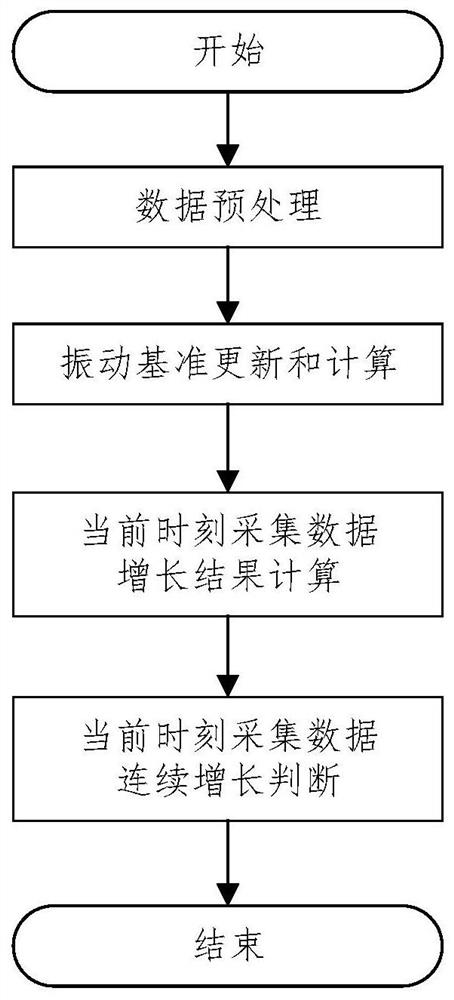
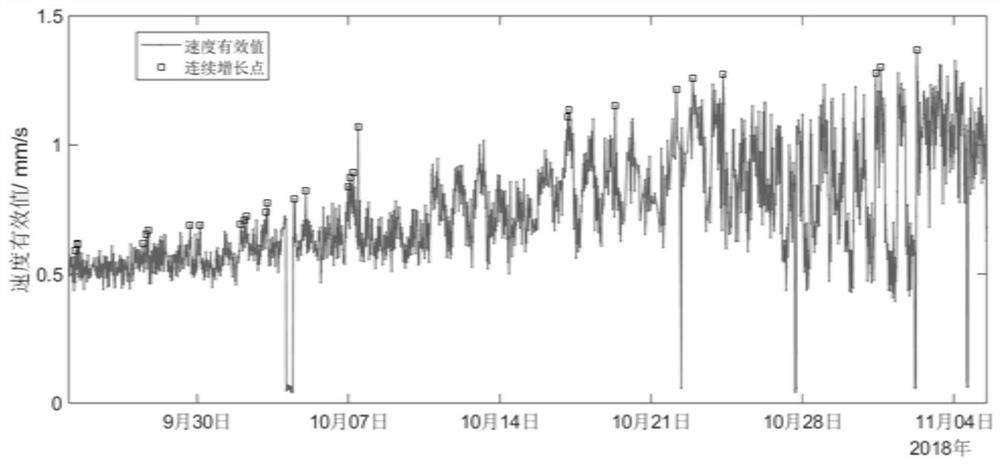
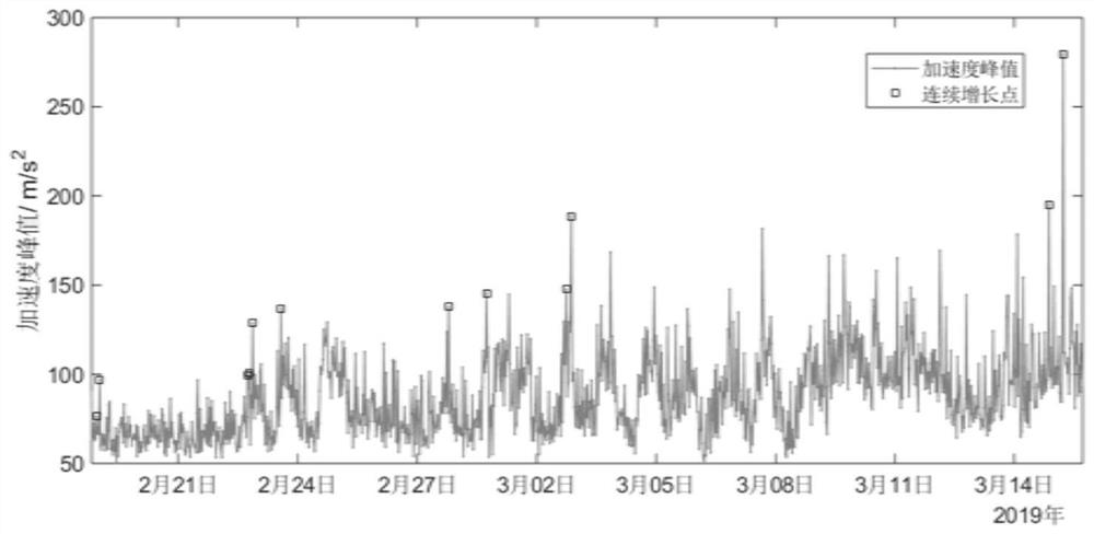
[0032] see Figure 1 to Figure 3 , an automatic detection technology for continuous growth of mechanical equipment vibration, comprising the following steps:

[0033] Step 1: Preprocessing the collected data at the current moment.

[0034] The vibration signal waveform data collected at the current moment of equipment vibration monitoring is subjected to feature extraction, and the extracted eigenvalue V is subjected to over-limit data cleaning and shutdown data cleaning preprocessing.

[0035] Over-limit cleaning: According to the measurable range of the vibration sensor of the equipment, judge whether the vibration characteristic value V collected at the current moment exceeds the range. If it exceeds the range, the vibration collected at the current moment is not available, and no follow-up analysis is required! Otherwise, you need to continue to the subsequent analysis ste...


PUM


Abstract

The invention discloses an automatic detection method for continuous increase of vibration of mechanical equipment. The automatic detection method comprises the following steps of: step 1, performingfeature extraction on vibration signal waveform data acquired at the current moment of equipment vibration monitoring; 2, updating and calculating a vibration reference, comparing a feature value V obtained in the step 1 with the vibration reference, and judging whether the vibration reference is to be updated or not; 3, calculating an increase result of the data collected at the current moment according to the vibration reference value; and 4, judging whether the data acquired at the current moment is continuously increased or not according to a calculation result in the step 3. According tothe method, the equipment vibration reference standard is automatically calculated and updated, then the increase results of the vibration and the reference standard are collected in real time throughcalculation equipment; whether the increase results are larger than the increase results corresponding to the previous continuous growth point or not is judged; and automatic detection of the continuous increase of equipment vibration is achieved.

Description

technical field [0001] The invention belongs to the field of state monitoring and predictive maintenance of mechanical equipment, and in particular relates to an automatic detection method for continuously increasing vibration of mechanical equipment. Background technique [0002] At present, more and more important high-value mechanical equipment has vibration sensors installed in its key parts to detect and discover component abnormalities and failures that occur during the operation of mechanical equipment. Abnormal operation and faults of mechanical equipment can be detected and discovered through changes in vibration growth trends. The continuous growth of equipment vibration is an important sign of equipment abnormality and failure. Therefore, detection and discovery of continuous vibration growth can provide an important analysis basis for mechanical equipment condition monitoring and predictive maintenance. [0003] Some existing trend growth detection methods are ...

Claims


Application Information

Patent Timeline
IPC IPC(8): G01H17/00G06K9/00
CPCG01H17/00G06F2218/08
Inventor 胡翔田秦吕芳洲夏立印
Owner 西安因联信息科技有限公司
Learn More