Pneumatic oil injection device and control method thereof

The technology of an oil injection device and a control method, which is applied in the direction of distribution device, engine components, engine lubrication, etc., can solve problems such as the inability to flexibly adjust the amount of grease, shaft seal failure due to lack of oil, and single oil supply lubrication mode, etc., to achieve Variety of lubrication modes, low manufacturing cost and good practicability

Pending Publication Date: 2021-03-19
德通智能科技股份有限公司
View PDF0 Cites 0 Cited by
  • Summary
  • Abstract
  • Description
  • Claims
  • Application Information

AI Technical Summary

Problems solved by technology

At present, in the concrete mixing industry, the lubrication method of the concrete mixing main engine is basically a self-lubricating mode in which an automatic oil injection machine is installed at each end of the mixing main engine. The existing automatic oil injection machine has a small oil output per time and a low oil output pressure. If the oil pipe is long, the oil will not come out smoothly or not. If the oil pipe is not properly arranged or the grease is not replenished in time, it will easily cause the shaft seal to lack oil and cause the shaft seal to fail. For multi-point lubrication, the grease cannot be flexibly adjusted according to the different needs of each lubrication point. Due to the disadvantages of quantity, and the oil supply lubrication method is relatively simple and the manufacturing cost is high. Therefore, there is an urgent need for a single output oil volume, high oil pressure, accurate timing, quantitative adjustment and controllable according to the needs of different lubrication points. Lubricating equipment with multiple lubrication modes and low manufacturing cost

Method used


Image

  • Pneumatic oil injection device and control method thereof
  • Pneumatic oil injection device and control method thereof
  • Pneumatic oil injection device and control method thereof

Examples


Embodiment 1

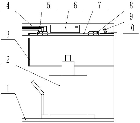
[0052] Such as figure 1 , figure 2 , image 3 , Figure 4 , Figure 5 with Figure 8As shown, a pneumatic oiling device includes an oiling machine 2, an oil separator 4, a control valve group 8 and a controller 6, the oiling machine 2 is a pneumatic oiling machine, the controller 6 is a PLC controller, and the controller 6 is provided with Two-color indicator light.

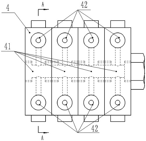
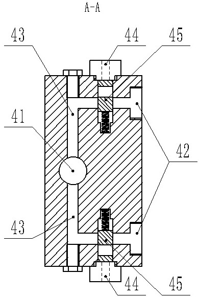
[0053] The oil separator 4 is connected in parallel with four reversing valves 40. The number of reversing valves 40 can be increased or decreased according to the number of lubricating points of the equipment used. It is economical and practical. Each reversing valve 40 is equipped with two first Spool port 44 and two first oil outlets 42, each first spool port 44 corresponds to one first oil outlet 42, and the first oil outlets 42 are respectively connected to the oil supply branch pipe 5, the oil supply branch pipe 5 is Composed of multiple lubricating oil pipes, the number of oil supply branch pipes 5 ...

Embodiment 2

[0066] The difference from Embodiment 1 is that the control method of the pneumatic oil injection device includes a sequential oil supply lubrication control method and a simultaneous oil supply lubrication control method.

[0067] Sequential oil supply lubrication control method: compressed air enters the oil injection machine 2 through the air pipe, the controller 6 controls the operation of the oil injection machine 2 through the program, and the oil injection machine 2 pumps the lubricating grease to the reversing valve in the oil separator 4 through the oil supply main pipe 3 The first main oil circuit 41 of 40, the lubricating grease enters the first oil distribution circuit 43 from the first main oil circuit 41, and the high-pressure air or the hydraulic oil pumped by the external hydraulic station enters the electromagnetic control valve group 8 through the external pipeline. The main circuit 81 of the valve 80, high-pressure air or hydraulic oil enters the branch circu...

Embodiment 3

[0070] Such as Image 6 with Figure 7 As shown, the difference from Embodiment 1 is that the oil separator 4 is a whole, and the oil separator 4 is provided with eight second oil outlets 47 and eight second spool ports 49, and each second spool port 49 Corresponding to one second oil outlet 47, the second oil outlet 47 is connected to the oil supply branch pipe 5 respectively, and the inside of the oil distributor 4 is provided with one second main oil circuit 46 and eight second oil distribution channels 48, the second oil distribution The roads 48 communicate with the second main oil circuit 46 respectively. One end of the second main oil circuit 46 in the oil separator 4 communicates with the oil injection machine 2 through the oil supply main pipe 3, and the other end is blocked with a plug.

[0071] Each outlet 83 of the solenoid valve 80 in the control valve group 8 communicates with the second spool port 49 on the corresponding oil separator 4 through the branch pipe ...


PUM


Abstract

The invention discloses a pneumatic oil injection device and a control method thereof. The pneumatic oil injection device comprises an oil injection machine, an oil distributor, a control valve bank and a controller, wherein the oil distributor is connected with the oil injection machine and the control valve bank; and the controller is electrically connected with the oil injection machine and thecontrol valve bank. The controller controls the oil injection machine through a program to pump oil into the oil distributor, and the controller realizes the condition that the oil distributor regularly and and quantitatively carries out fixed-point or multi-point oil supply lubrication on lubricating points of use equipment through program control, so that partial oil supply lubrication controland complete oil supply lubrication control be realized, and sequential oil supply lubrication control and simultaneous oil supply lubrication control can be realized; the pneumatic oil injection device is low in manufacturing cost and high in intelligence; and when abnormal conditions happen, automatic shutdown or automatic pressure relief can be achieved, and abnormal indication is achieved through light, so that the operation quality of the equipment is improved, and the safety and reliability are achieved.

Description

technical field [0001] The invention belongs to the technical field of grease lubricating machinery, and in particular relates to a pneumatic oil injection device and a control method thereof. Background technique [0002] The oil injection machine is an auxiliary equipment used to add lubricating oil to machines and other equipment in the process of industrial production, and is an indispensable tool for industrial production. At present, in the concrete mixing industry, the lubrication method of the concrete mixing main engine is basically a self-lubricating mode in which an automatic oil injection machine is installed at each end of the mixing main engine. The existing automatic oil injection machine has a small oil output per time and a low oil output pressure. If the oil pipe is long, the oil will not come out smoothly or not. If the oil pipe is not properly arranged or the grease is not replenished in time, it will easily cause the shaft seal to lack oil and cause the ...

Claims


Application Information

Patent Timeline
Patent Type & Authority Applications(China)
IPC IPC(8): F16N7/38F16N25/00F16N29/04
CPCF16N7/38F16N25/00F16N29/04
Inventor 张良奇李冠峰李鹏翟志辉
Owner 德通智能科技股份有限公司
Why Eureka
Try Eureka