Processing device for agricultural Internet of Things equipment part production
A technology of Internet of Things equipment and processing equipment, applied in heat treatment equipment, manufacturing tools, furnaces, etc., can solve problems such as damage and high pressure
- Summary
- Abstract
- Description
- Claims
- Application Information
AI Technical Summary
Problems solved by technology
Method used
Image
Examples
Embodiment 1
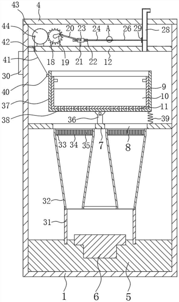
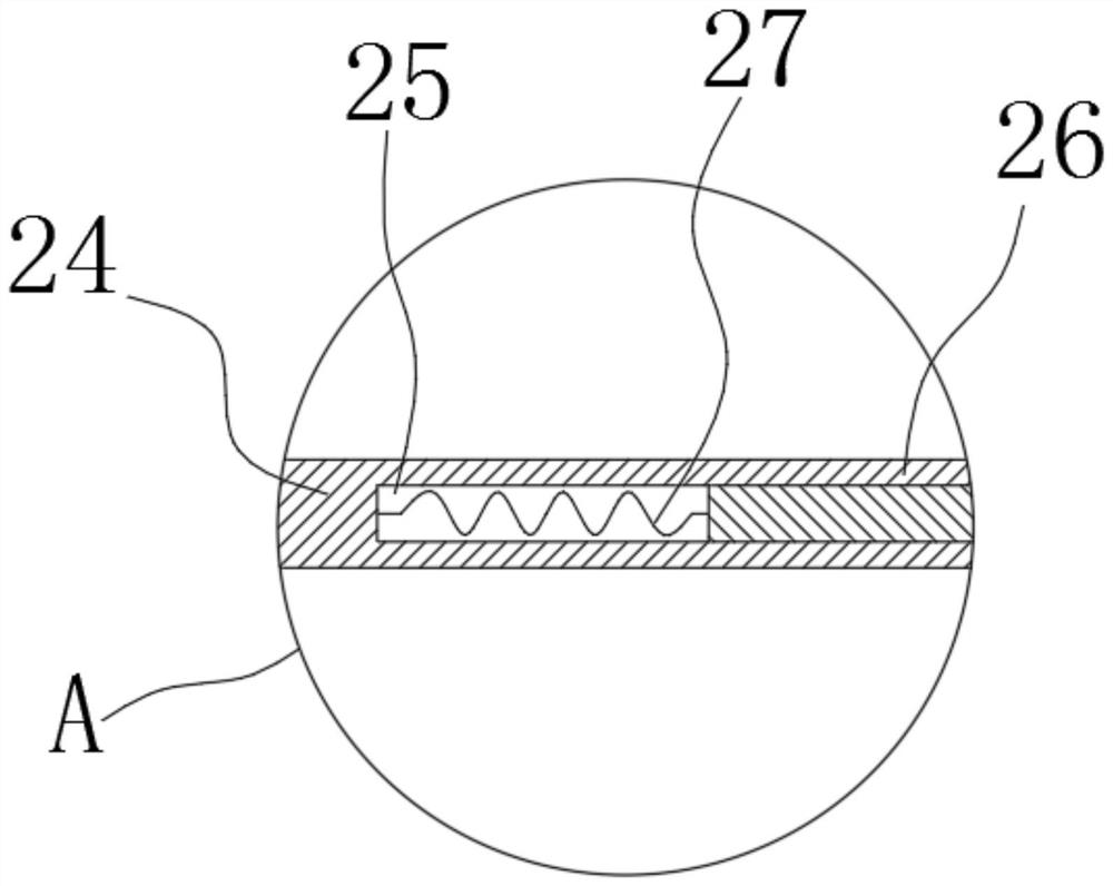
[0023] refer to Figure 1-6 , a processing device for the production of agricultural Internet of things equipment components, including a heating box 1, an opening 2 is opened on the heating box 1, a sliding door 3 is rotatably connected to the opening 2, and a top plate 4 is connected to the upper end of the heating box 1 , the inner bottom of the heating box 1 is connected with a fixed frame 5, the fixed frame 5 is used to fix the heating plate 6, the upper end of the fixed frame 5 is connected with the heating plate 6, and the heating box 1 is connected with the first heat insulation board 7, the first The heat insulation board 7 is located on one side of the opening 2, and both sides of the first heat insulation board 7 are provided with first through holes 8, the first through holes 8 allow hot air to pass through the first heat insulation board 7, and the first heat insulation board 7 The upper end of the plate 7 is placed with a material holding mechanism, and the mater...
Embodiment 2
[0027] The hot gas heated by the heating plate 6 moves upwards. Since there is a certain space in the heating box 1, the gas moving upwards is scattered, and the direction of the gas flowing out from the first through hole 8 is chaotic, which reduces the heat treatment effect of the parts. Refer to Figure 1-6 , as another preferred embodiment of the present invention, the difference from Embodiment 1 is that the upper end of the fixed frame 5 is plugged with a box body 31, the heating plate 6 is located in the box body 31, and both sides of the upper end of the box body 31 are connected with guides. Air bucket 32, the upper end of each air guide bucket 32 is matched with the fourth through hole 38, the inner upper end of each air guide bucket 32 is connected with a support frame 33, and the upper end of each support frame 33 is connected with a dispersion plate 34 , each dispersing plate 34 is provided with several third through holes 35 .
[0028] Working process: the bo...
Embodiment 3
[0030] The hot air coming out from the third through hole 35 contacts with the bottom of the material box 9 to heat the parts at the inner bottom of the material box 9, and the parts in the material box 9 are in a stacked state, and the internal parts cannot be heated with the hot air. Direct contact reduces the effect of heat treatment, refer to Figure 1-6 , as another preferred embodiment of the present invention, the difference from Embodiment 1 is that the upper end of the first heat shield 7 is connected with a support column 36, the support column 36 is located between the two first through holes 8, and the support column 36 The upper end is rotatably connected with a support frame 37, and the support frame 37 is used to place the material holding mechanism. After the support frame 37 rotates, it rotates along the length direction of the heating box 1. The bottom end of the support frame 37 is provided with several fourth through holes 38. The bottom end of the support ...
PUM
 Abstract
Description
Claims
Application Information
 - R&D
- Intellectual Property
- Life Sciences
- Materials
- Tech Scout
- Unparalleled Data Quality
- Higher Quality Content
- 60% Fewer Hallucinations
Browse by: Latest US Patents, China's latest patents, Technical Efficacy Thesaurus, Application Domain, Technology Topic, Popular Technical Reports.
© 2025 PatSnap. All rights reserved.Legal|Privacy policy|Modern Slavery Act Transparency Statement|Sitemap|About US| Contact US: help@patsnap.com


