Transfer device for reactor in power transformation system and method

A technology of transfer device and reactor, which is applied in the direction of winch device, transportation and packaging, lifting equipment braking device, etc., can solve the problems of saving transfer device and manpower, disadvantages, etc., and achieve high support and fixation accuracy, high transfer efficiency, The effect of ensuring the stability of the structure

Active Publication Date: 2021-03-19
STATE GRID SHANDONG ELECTRIC POWER CO JINING CITY RENCHENG DISTRICT POWER SUPPLY CO +2
View PDF7 Cites 0 Cited by
  • Summary
  • Abstract
  • Description
  • Claims
  • Application Information

AI Technical Summary

Problems solved by technology

However, since the installation of the reactor needs to ensure a certain accuracy, this method is affected by the structure of the crane itself, resulting in the installation of the reactor requiring long-term positioning, and the transportation and hoisting equipment are separated, which is not conducive to effective saving of transfer devices and manpower

Method used


Image

  • Transfer device for reactor in power transformation system and method
  • Transfer device for reactor in power transformation system and method

Examples


Embodiment 1

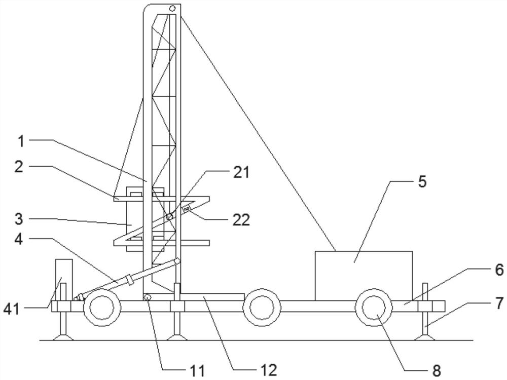
[0030] A transfer device for a reactor in a substation system, characterized in that it includes a support connected to a base, an overturning system and a lifting system;

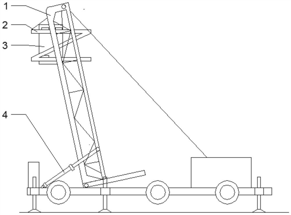
[0031] The support 1 is slidingly connected to the rotating shaft of the Z-shaped bracket 2. The Z-shaped bracket 2 includes an upper strut and a lower strut, and the two struts can support the supporting part on the side of the reactor. The Z-shaped bracket The frame 2 supports the reactor 3 to move up and down and rotate in the chute of the bracket 1; the lifting system includes a winch 5 machine and a steel wire rope, and the steel wire rope goes around the top of the bracket to connect with the Z-shaped bracket; the turning system includes a turning shaft 11, the The support 1 is rotationally connected with the base 6 through the turning shaft 11, the turning shaft 11 passes through the bottom of the support 1 and is located on one side of the support 1, and the other side of the support 1 is rotational...

Embodiment 2

[0037] The support 1 is slidingly connected to the rotating shaft of the Z-shaped bracket 2. The Z-shaped bracket 2 includes an upper strut and a lower strut, and the two struts can support the supporting part on the side of the reactor. The Z-shaped bracket The frame 2 supports the reactor 3 to move up and down and rotate in the chute of the bracket 1; the lifting system includes a winch 5 machine and a steel wire rope, and the steel wire rope goes around the top of the bracket to connect with the Z-shaped bracket; the turning system includes a turning shaft 11, the The support 1 is rotationally connected with the base 6 through the turning shaft 11, the turning shaft 11 passes through the bottom of the support 1 and is located on one side of the support 1, and the other side of the support 1 is rotationally connected with one end of the hydraulic push rod 4, and the hydraulic push rod 4 The other end is rotatably connected with the base 6 .

[0038]It also includes a walking...


PUM


Abstract

The invention discloses a transfer device for a reactor in a power transformation system and a method. The transfer device comprises a support, an overturning system and a lifting system which are allconnected with a base, wherein the support is connected with a rotating shaft of a Z-shaped bracket in a sliding mode, and the Z-shaped bracket is used for supporting the reactor; the lifting systeminvolves a winch and a steel wire rope, and the steel wire rope bypasses the top of the support to be connected with the Z-shaped bracket; the overturning system involves an overturning shaft and a hydraulic push rod, and the overturning shaft and the hydraulic push rod are arranged on the two opposite side faces of the support correspondingly and rotationally connected with the base at the same time; and the overturning shaft axially penetrates through the support, and the support can rotate around the overturning shaft. When standby equipment of the extra-high voltage reactor and a transformer needs to be replaced due to some reasons, the reactor can be transferred to the transfer device from a mounting position, so that direct transportation is achieved, simpleness and convenience are achieved, and the transfer efficiency is high.

Description

technical field [0001] The present disclosure relates to a reactor transfer device and method in a power transformation system. Background technique [0002] With the construction and development of national high-voltage and ultra-high-voltage power grids, reactors and transformers, which are the backbone equipment of power transformation systems, will be more widely used. When the high-voltage test reactor needs to be replaced with spare equipment due to some reasons, the traditional operation method needs to hoist the reactor to the transport vehicle with a hoisting vehicle, and hoist the spare equipment on the transport vehicle to the installation position of the reactor. However, since the installation of the reactor needs to ensure a certain accuracy, this method is affected by the structure of the crane itself, resulting in the installation of the reactor requiring long-term positioning, and the transportation and hoisting equipment are separated, which is not conduciv...

Claims


Application Information

Patent Timeline
IPC IPC(8): B66C23/00B66C5/00B66C13/08B66C13/20B66C13/00
CPCB66C23/00B66C5/00B66C13/08B66C13/20B66C13/00Y02E30/30
Inventor 王峰边宁张慧陶乃绘楚凯楠王延梅谢继信周奇钱聪周中华孟德彦范冉唐亮王昌庭褚婷
Owner STATE GRID SHANDONG ELECTRIC POWER CO JINING CITY RENCHENG DISTRICT POWER SUPPLY CO
Why Eureka
Try Eureka