
Standby zero reactive power consumption control circuit in switching power supply

A technology for controlling circuits and switching power supplies, which is applied in electronic switches, electrical components, pulse technology, etc., and can solve problems such as dangerous currents and low power factors

Pending Publication Date: 2021-03-16
SHENZHEN GOLD POWER TECH
View PDF0 Cites 0 Cited by
  • Summary
  • Abstract
  • Description
  • Claims
  • Application Information

AI Technical Summary

Problems solved by technology

[0004] The present invention aims at current switching power supply, utilizes the switch arranged between the PFC circuit and the power supply to disconnect when the PFC is not working, and cuts off the connection between the reactive device in the PFC and the AC power grid, thereby preventing the reactive power of the PFC from being When the device is connected to the AC grid, the power factor will be low, and a large current will be generated at the moment when the PFC is connected to the AC grid, which will cause dangerous problems. Provide a zero reactive power consumption control circuit in the switching power supply

Method used


Image

  • Standby zero reactive power consumption control circuit in switching power supply

Examples


Embodiment 1

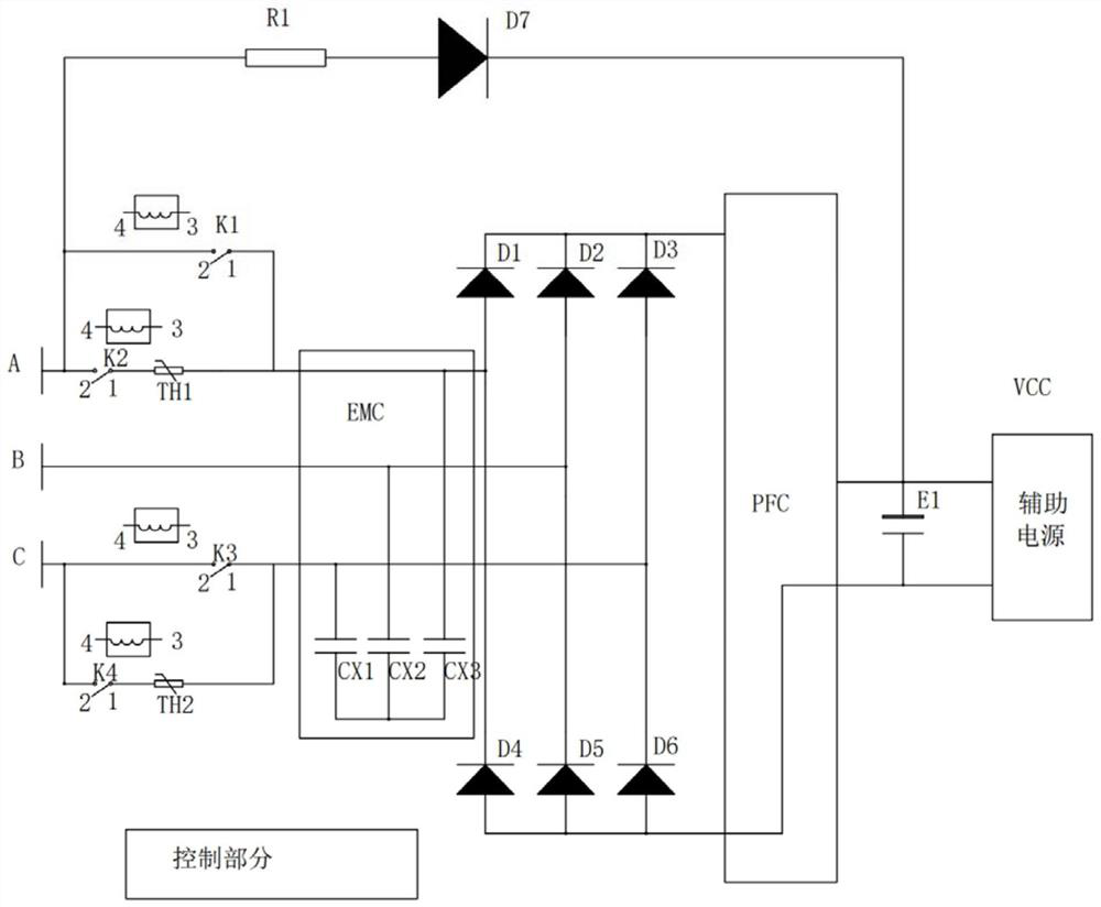
[0017] Embodiment 1, this embodiment is a standby zero reactive power consumption control circuit in a three-phase switching power supply in a charging pile module. In practice, the switching power supply with two-phase AC mains current can also use the standby zero reactive power consumption control circuit in the switching power supply.

[0018] like figure 1 Shown: The connection points A, B, and C in the figure are the input of the three-phase power grid, respectively. The switch circuit composed of relays K1, K2, K3, K4 and thermistors TH1 and TH2 is called the zero reactive power control circuit here. The first main control switch K1 is the relay K1, the third main control switch K3 is the relay K3, the second sub-control switch K2 is the relay K2, and the fourth sub-control switch K4 is the relay K4. In practice, the relays K1, K2, K3 , K4 or other electronic switches such as MOS tube, IGBT, controllable silicon, etc.

[0019] Capacitors CX1, CX2, and CX3 represent si...


PUM


Abstract

The invention discloses a standby zero reactive power consumption control circuit in a switching power supply, which comprises a main control switch arranged between a PFC circuit in the switching power supply and an AC power supply network, and is characterized in that the main control switch is switched off under the control of the control circuit when the PFC circuit does not work; the controlcircuit is characterized by further comprising an auxiliary control switch and a current-limiting resistor, the auxiliary control switch and the current-limiting resistor are connected in series and then connected to the two ends of the main control switch in parallel, and the control circuit controls the auxiliary control switch to be closed for set delay time and then controls the main control switch to be closed when the switching power supply is connected to a load. According to the invention, when the switching power supply is connected to an alternating-current power grid, the two ends of the main control switch are connected in parallel with the circuit formed by the series connection of the auxiliary control switch and the current-limiting resistor, and then the auxiliary control switch is controlled to be closed, so that the current in capacitors, inductors and other devices in the PFC is saturated with small current due to the limitation of the current-limiting resistor; andthen the main control switch is closed to reduce the instantaneous current.

Description

technical field [0001] The invention relates to a standby zero reactive power consumption control circuit in a switching power supply. Background technique [0002] The switching power supply is an important part of the switching power supply in the charging device. It converts the commercial power into a DC power supply for charging the car. The front stage of the switching power supply generally has a PFC circuit. When the PFC circuit works, a high power factor can be obtained. When the circuit is not working, because the capacitors and inductors at the input end are still connected to the AC power grid, they will consume a lot of reactive power, resulting in a low power factor. [0003] The common practice is to use a switch such as a controllable air switch or a contactor at the input end of the power grid. When the PFC circuit is not working, the switch is turned off by a control signal to cut off the power supply of the rear reactive devices. However, since the resist...

Claims


Application Information

Patent Timeline
Patent Type & Authority Applications(China)
IPC IPC(8): H03K17/18H03K17/687
CPCH03K17/18H03K17/687
Inventor 韩龙腾蒋中为
Owner SHENZHEN GOLD POWER TECH
Learn More