
Multi-channel switching circuit, switching method

A switching circuit, multi-channel technology, applied in the direction of logic circuit connection/interface layout, logic circuit coupling/interface using field effect transistors, etc. Voltage, low rate of change, effect of reducing influence

Active Publication Date: 2021-08-10
QITAN TECH LTD CHENGDU
View PDF0 Cites 0 Cited by
  • Summary
  • Abstract
  • Description
  • Claims
  • Application Information

AI Technical Summary

Problems solved by technology

However, the application of multiplexing switches often does not consider the crosstalk caused by the switching of the current channel to adjacent channels, and this crosstalk has a great influence on the results in the measurement of dense channels and weak signals

Method used


Image

  • Multi-channel switching circuit, switching method
  • Multi-channel switching circuit, switching method
  • Multi-channel switching circuit, switching method

Examples


Embodiment Construction

[0026] The characteristics and exemplary embodiments of various aspects of the present invention will be described in detail below. In order to make the purpose, technical solutions and advantages of the present invention clearer, the present invention will be further described in detail below in conjunction with the accompanying drawings and specific embodiments. It should be understood that the specific embodiments described here are only intended to explain the present invention rather than limit the present invention. It will be apparent to one skilled in the art that the present invention may be practiced without some of these specific details. The following description of the embodiments is only to provide a better understanding of the present invention by showing examples of the present invention.

[0027] It should be noted that in this article, relational terms such as first and second are only used to distinguish one entity or operation from another entity or operati...


PUM


Abstract

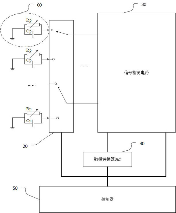
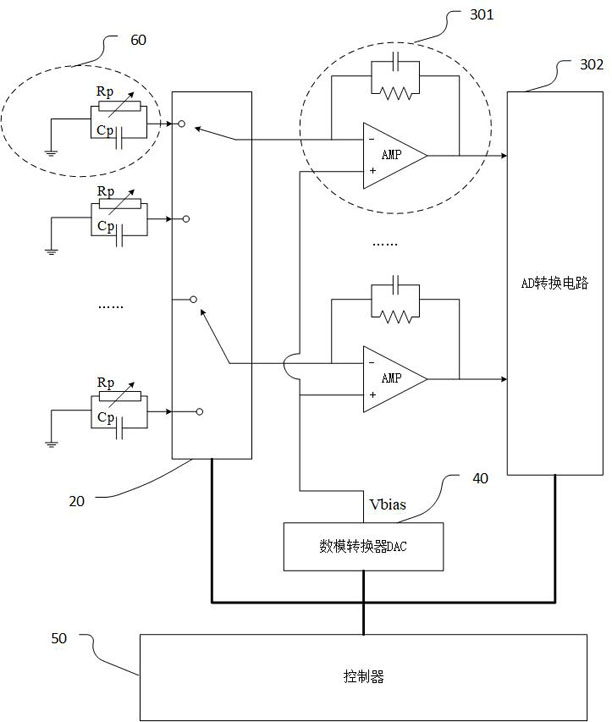
The embodiment of the present invention provides a multi-channel switching circuit and switching method, including: a multiplexing switch matrix, the control terminal of the multiplexing switch matrix is ​​connected to a controller; the multiplexing switch matrix includes a plurality of multiplexing Using a switch, each output channel of each multiplexing switch is respectively connected to a sensor circuit; the common end of each multiplexing switch is respectively connected to the first input end of the signal detection circuit; the output end of the signal detection circuit is connected to the control device, the second input end of the signal detection circuit is connected to the output end of the digital-to-analog converter DAC; the input end of the digital-to-analog converter DAC is connected to the controller; the controller is used to control the digital-to-analog conversion when the multiplexing switch switches the output channel The DAC adjusts the bias voltage applied to the input channel of the multiplexing switch according to a preset gradient function. According to the switching circuit of the embodiment of the present invention, the instantaneous current and voltage generated during channel switching can be reduced, thereby reducing the influence on adjacent channels.

Description

technical field [0001] The invention belongs to the field of gene sequencing, and in particular relates to a multi-channel switching circuit and a switching method. Background technique [0002] The nanopore array of the nanopore sequencer has hundreds or thousands of nanopores for gene sequencing. However, not all nanopores in a nanopore array remain usable after production or during sequencing. In order to improve data acquisition efficiency, reduce cost and save space, signal acquisition systems often group multiple nanopores into one group, and select the one with the best quality from the multiple nanopores for sequencing; therefore, during the sequencing process, Switch among multiple wells in real time based on the state of the wells. [0003] In common circuit design, multiplexing switches are often used to select a target channel from multiple input channels for subsequent signal processing. However, the application of multiplexing switches often does not conside...

Claims


Application Information

Patent Timeline
Patent Type & Authority Patents(China)
IPC IPC(8): H03K19/0185
CPCH03K19/0185
Inventor 王琎胡庚胡喜
Owner QITAN TECH LTD CHENGDU
Learn More