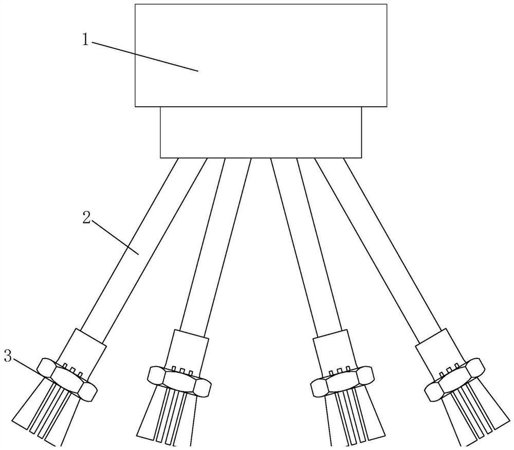
Novel secondary short-circuit wire of current transformer

A technology of secondary short-circuiting and current transformer, applied in the direction of inductor, transformer/inductor coil/winding/connection, transformer/inductor components, etc. Economic, safety, reliability and other issues, to achieve the effect of reducing damage, good elasticity and high strength

Pending Publication Date: 2021-03-16
GUIZHOU POWER GRID CO LTD
View PDF5 Cites 1 Cited by
  • Summary
  • Abstract
  • Description
  • Claims
  • Application Information

AI Technical Summary

Problems solved by technology

One is to short-circuit the secondary sides A, B, C, and N end-to-end with three test short-circuit wires. Although this method is simple, there is a risk of secondary open circuit of the current transformer caused by accidental contact, and waste of materials is not economical. Safety and Reliability Requirements
The second is to short-circuit with terminal short-circuits. Although the short-circuit is reliable, the number of terminal short-circuit terminals is not flexible, and it does not have the disadvantages of repeated use and cannot meet the actual requirements of the site.

Method used


Image

  • Novel secondary short-circuit wire of current transformer
  • Novel secondary short-circuit wire of current transformer
  • Novel secondary short-circuit wire of current transformer

Examples


Embodiment Construction

[0031] The following will clearly and completely describe the technical solutions in the embodiments of the present invention with reference to the accompanying drawings in the embodiments of the present invention. Obviously, the described embodiments are only some, not all, embodiments of the present invention.

[0032] Examples of the described embodiments are shown in the drawings, wherein like or similar reference numerals designate like or similar elements or elements having the same or similar functions throughout. The embodiments described below by referring to the figures are exemplary and are intended to explain the present invention and should not be construed as limiting the present invention.

[0033] In describing the present invention, it should be understood that the terms "center", "longitudinal", "transverse", "length", "width", "thickness", "upper", "lower", "front", " Back", "Left", "Right", "Vertical", "Horizontal", "Top", "Bottom", "Inner", "Outer", "Clock...


PUM


Abstract

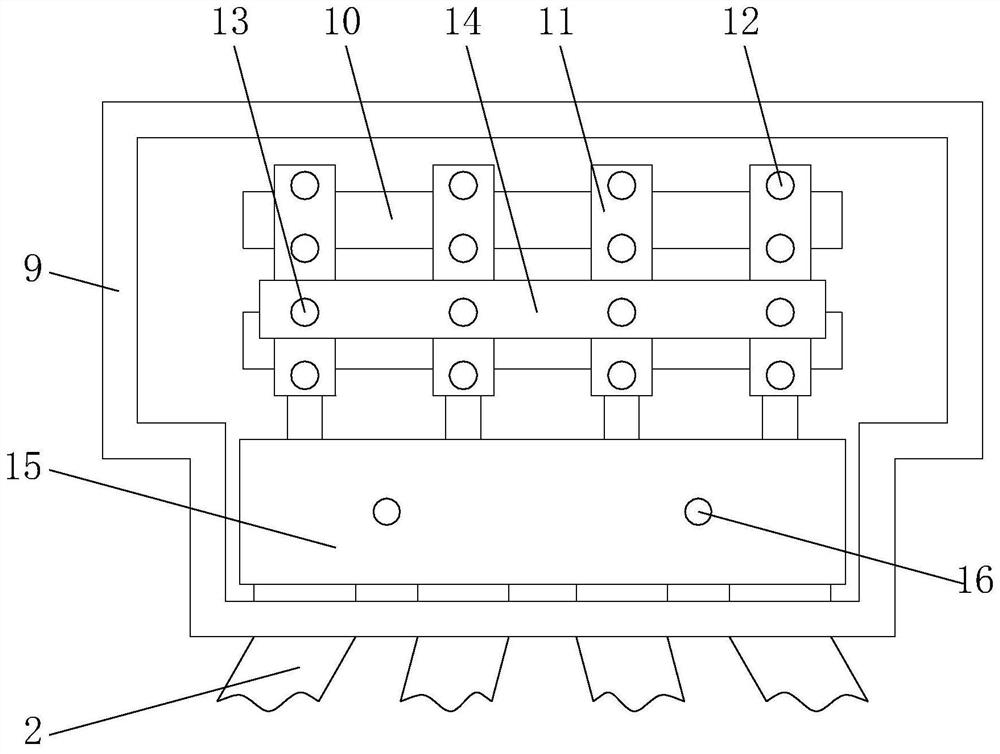
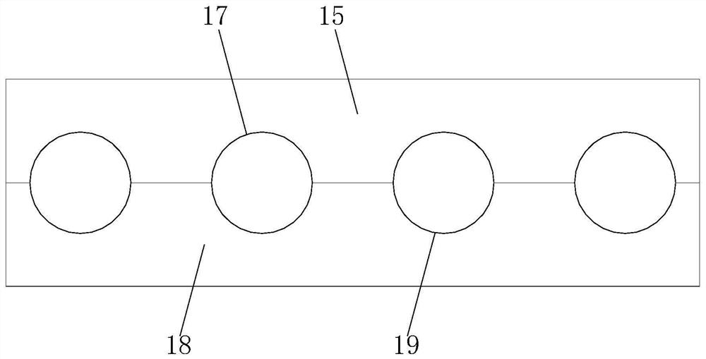
The invention discloses a novel secondary short-circuit wire of a current transformer. The novel secondary short-circuit wire comprises a connecting box, a short-circuit wire and a connector lug, theconnecting box comprises a box body, an insulating base, a connector base, a fixing screw, a connecting screw, a connecting plate, an upper fixing plate, a fixing buckle, an upper fixing groove, a lower fixing plate, a lower fixing groove, a wiring hole and a screw hole, the insulating base is fixedly installed on a back plate of the box body, the connector base is fixedly installed on the insulating base, the wiring hole is formed in the middle of the wire holder, the screw hole is perpendicular to the wiring hole and formed in the connector base, the connecting screw is in threaded connection with the screw hole, the connecting plate is fixedly connected with the screw hole through the connecting screw, the lower fixing plate is fixedly installed below the insulating base, the lower fixing groove is formed in the lower fixing plate, and the upper fixing plate is fixedly connected with the lower fixing plate through the fixing bucckle. According to the invention, the problems that anopen circuit risk is caused by false touch of a short circuit wire and the arrangement of a terminal short circuit sheet is not flexible are solved.

Description

technical field [0001] The invention relates to the technical field of current transformers, in particular to a new type of secondary short wiring for current transformers. Background technique [0002] A current transformer is an instrument that converts a large current on the primary side into a small current on the secondary side for measurement based on the principle of electromagnetic induction. A current transformer consists of a closed core and windings. Its primary side winding has few turns and is connected in series with the current line to be measured. Therefore, it often has all the current of the line flowing, and the number of turns of the secondary side winding is relatively large. It is connected in series with the measuring instrument and the protection circuit. When the current transformer is working, its secondary side circuit is always closed, so the measurement The impedance of the series coil of the instrument and the protection circuit is very small,...

Claims


Application Information

Patent Timeline
IPC IPC(8): H01R31/08H01R4/30H01B3/28H01B7/18H01B7/28H01B7/295H01B7/02H01B7/04H01F27/28H01F27/29H01F38/28
CPCH01R31/08H01R31/085H01R4/30H01B7/1875H01B7/1895H01B7/2813H01B7/2806H01B7/0208H01B3/28H01B7/04H01B7/295H01F38/28H01F27/2828H01F27/29
Inventor 陈青松廖翼代康为汤卫伍拥军龙黔姜玉文孙伟田山杨颐熊文石炳堂田飞龙曹裕谋王龙郑文颜世强邓华张旭沈正康杨小军王志甫赵胜谢菲杨锴刘佳杨昌碑方曦李姜娴
Owner GUIZHOU POWER GRID CO LTD
Why Eureka
Try Eureka