Automatic regulation and control equipment of Hall current laser resistor trimming machine

A technology of laser resistance adjustment and Hall current, which is applied in the manufacture of resistors, resistors, and measurement of resistance/reactance/impedance, etc. It can solve the problems of not having a closed space, endangering the health of workers, and not having a device that absorbs and emits poisonous gas.

Active Publication Date: 2021-03-16
浙江森尼克半导体有限公司
View PDF14 Cites 0 Cited by
  • Summary
  • Abstract
  • Description
  • Claims
  • Application Information

AI Technical Summary

Problems solved by technology

[0003] However, during the long-term use of the traditional laser resistor trimming machine, because the laser beam hits the thick and thin film resistors, the resistors are vaporized and evaporated to realize the cutting of the thick and thin film circuits, and the gas produced is toxic and harmful. It will inhale a large amount of gas. The original laser resistance adjustment machine does not have a closed space, nor does it have a device for absorbing and discharging poisonous gas. The toxic and harmful gas produced is directly discharged into the air, which endangers the health of workers and pollutes the environment.

Method used


Image

  • Automatic regulation and control equipment of Hall current laser resistor trimming machine
  • Automatic regulation and control equipment of Hall current laser resistor trimming machine
  • Automatic regulation and control equipment of Hall current laser resistor trimming machine

Examples


Embodiment Construction

[0024] The technical solutions in the embodiments of the present invention will be clearly and completely described below in conjunction with the accompanying drawings in the embodiments of the present invention. Obviously, the described embodiments are only some of the embodiments of the present invention, not all of them. Based on The embodiments of the present invention and all other embodiments obtained by persons of ordinary skill in the art without making creative efforts belong to the protection scope of the present invention.

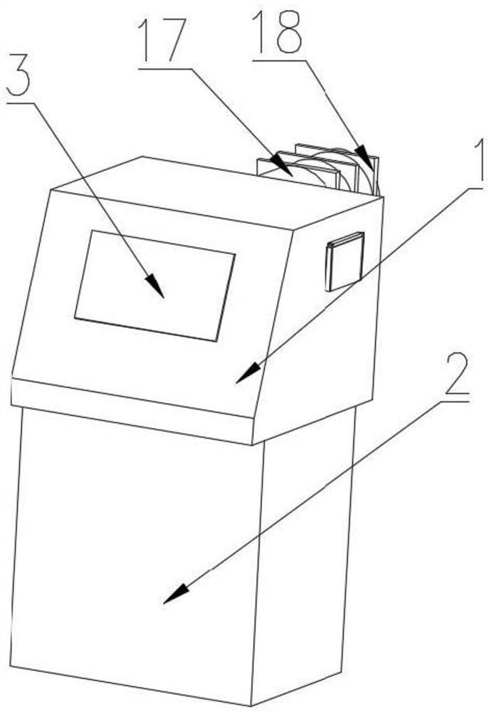
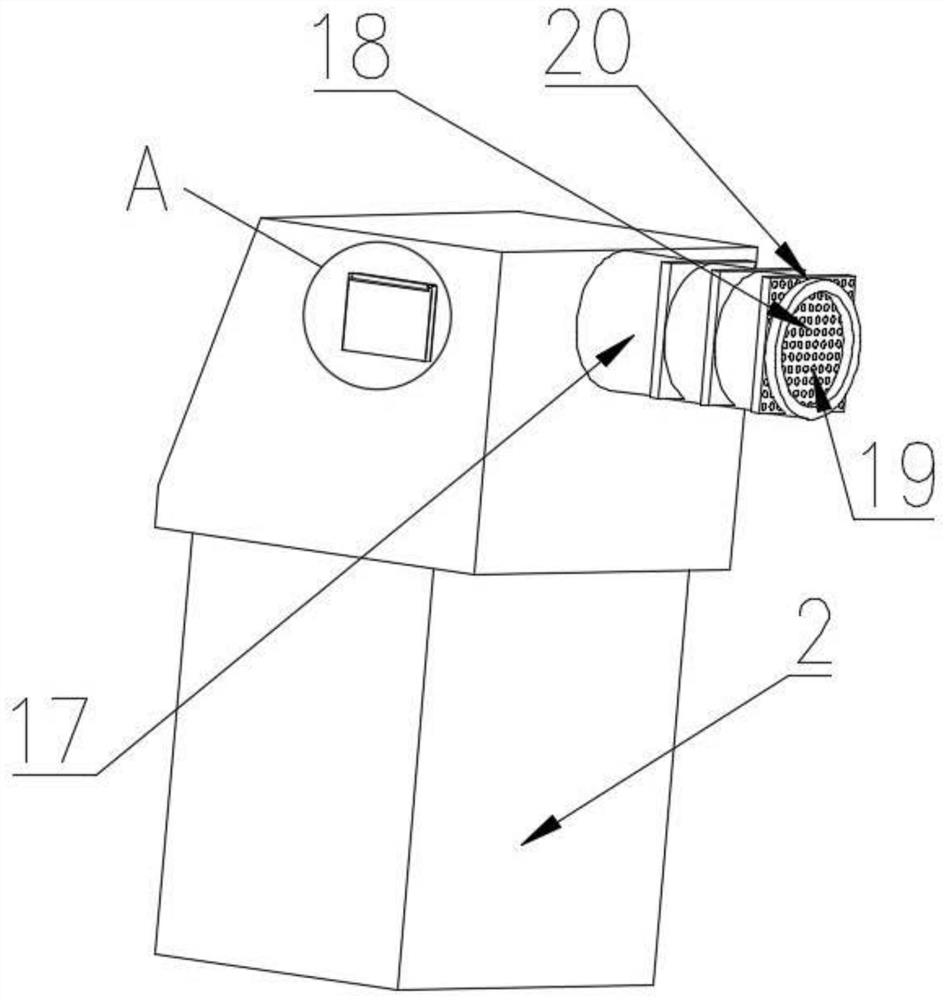
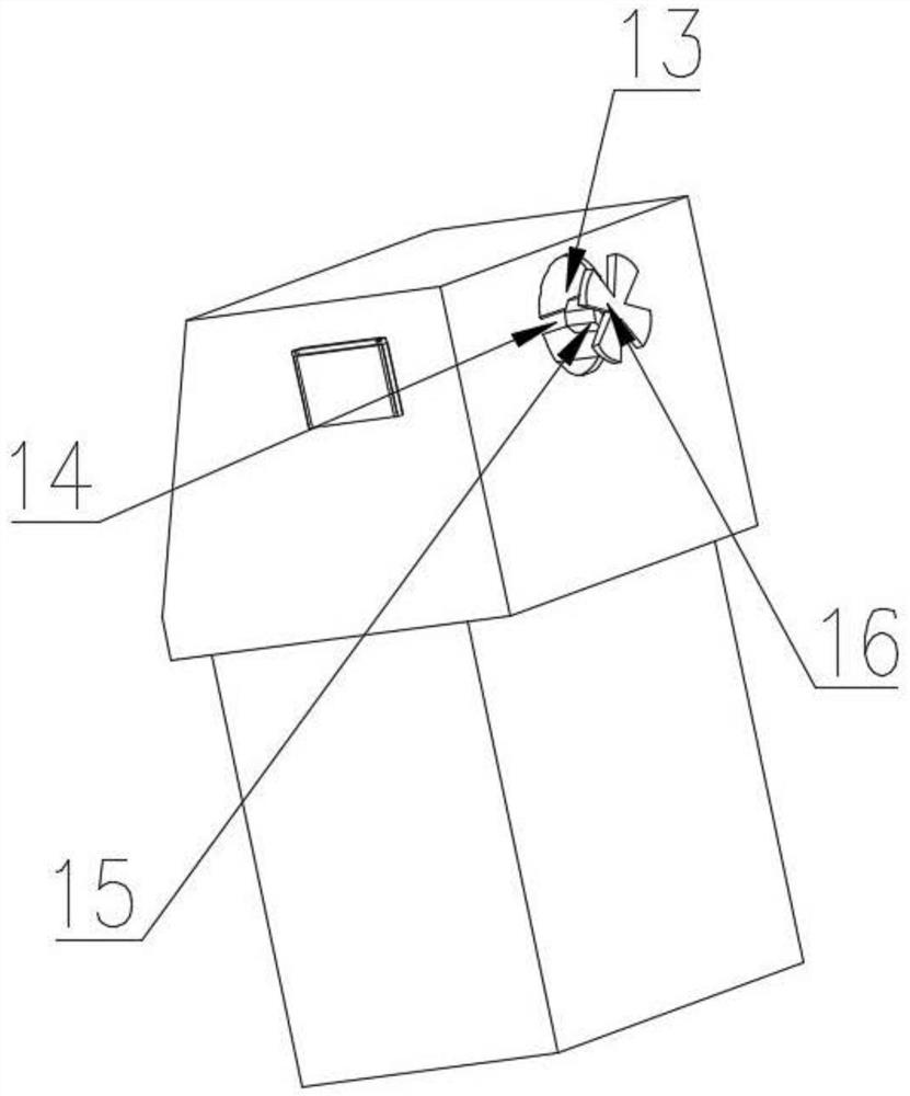
[0025] see Figure 1-5 , the present invention provides a technical solution, an automatic control device for a Hall current laser resistance adjustment machine, including an operation table 1, a support leg 2 and an operation screen 3, the operation screen 3 is equipped with a hydraulic rod 10 and a lifting rod 11 that can be controlled, It is also possible to adjust the function of the laser head 9 sliding on the chute 8. There is a discharge ...


PUM


Abstract

The invention relates to the field of laser resistance trimming machines, and discloses automatic regulation and control equipment of a Hall current laser resistance trimming machine. The equipment comprises an operation table, support legs and an operation screen, wherein a discharge port is formed in the middle of the upper portion of one side of the operation table, a sleeve rod is fixedly mounted at the top of the discharge port, and a rotating rod movably sleeves the interior of a hole formed in one end of the sleeve rod in a penetrating manner. According to the automatic regulation and control equipment of the Hall current laser resistor trimming machine, an air outlet hole is formed in the middle of the upper portion of the other side of an operation table and used for exhausting toxic gas generated by internal laser resistor trimming, a supporting rod is fixedly installed in the middle of the air outlet hole, a motor is fixedly installed in the middle of one side of the supporting rod, fan blades movably sleeve the middle of the top end of the motor, the motor is used for driving the fan blades to rotate to discharge internal toxic gas, the air outlet hole is movably sleeved with a vent pipe, a groove is formed in one side of the outer wall of the vent pipe, and an activated carbon plate is movably sleeved with the groove for slight ventilation, so that the toxic gas can stay in the interior for a longer time, and the adsorption effect is improved.

Description

technical field [0001] The invention relates to the field of laser resistance adjustment machines, in particular to an automatic control device for a Hall current laser resistance adjustment machine. Background technique [0002] The principle of laser resistance adjustment is to use a very thin laser beam to hit the thick and thin film resistors, and realize the cutting of thick and thin film circuits by vaporizing and evaporating the resistors. Change the geometric shape of the thick and thin film resistors to change the resistance value of the resistor. As the laser cutting process proceeds, the real-time measurement circuit monitors the change of the resistance value of the thick and thin film resistors in real time, and the resistance of the thick and thin film resistors is constantly approaching the target resistance value. , when the thick and thin film resistance reaches the target resistance value, the laser beam is turned off, that is, the laser resistance adjustme...

Claims


Application Information

Patent Timeline
Patent Type & Authority Applications(China)
IPC IPC(8): H01C17/242G01B7/06G01R27/02
CPCH01C17/242G01B7/06G01R27/02
Inventor 郑律杭洋
Owner 浙江森尼克半导体有限公司
Why Eureka
Try Eureka