Focusing device, optical imaging system, image capturing module and electronic device
An optical imaging system and focusing technology, which is applied in the field of optical imaging, can solve problems such as complex calibration process and long auto-focus response time, and achieve the effect of clear and uniform focusing imaging, satisfying the camera experience, and reducing the thickness
- Summary
- Abstract
- Description
- Claims
- Application Information
AI Technical Summary
Problems solved by technology
Method used
Image

Examples
no. 1 example
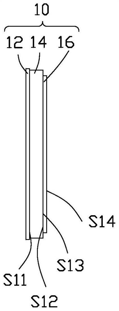
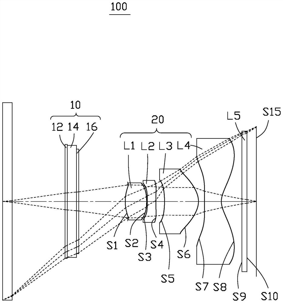
[0105] Please also refer to figure 2 and Figure 6 , the optical imaging system 100 of the first embodiment includes a cover glass, a protective layer 12, a light guide layer 14, an electro-deformable layer 16, a first lens L1, a second lens L2, and a third lens in order from the object side to the image side L3, a fourth lens L4 and an infrared filter L5.
[0106] Wherein, the object side S1 of the first lens L1 is convex at the near optical axis, and the image side S2 is convex at the near optical axis; the object side S3 of the second lens L2 is concave at the near optical axis; the third lens L3 The object side S5 is concave at the near optical axis, and the image side S6 is convex at the near optical axis; the object side S7 of the fourth lens L4 is concave at the near optical axis, and the image side S8 is concave at the near optical axis.
[0107] The object side and the image side of the protective layer 12 , the light guide layer 14 , and the electro-deformable lay...
no. 2 example
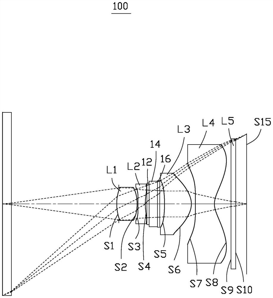
[0119] Please also refer to Figure 7 and Figure 8 , the optical imaging system 100 of the second embodiment includes a cover glass, a protective layer 12, a light guide layer 14, an electro-deformable layer 16, a first lens L1, a second lens L2, and a third lens in order from the object side to the image side L3, a fourth lens L4 and an infrared filter L5.
[0120] Wherein, the object side S1 of the first lens L1 is convex at the near optical axis, and the image side S2 is convex at the near optical axis; the object side S3 of the second lens L2 is concave at the near optical axis; the third lens L3 The object side S5 is concave at the near optical axis, and the image side S6 is convex at the near optical axis; the object side S7 of the fourth lens L4 is concave at the near optical axis, and the image side S8 is concave at the near optical axis.
[0121] The object side and the image side of the protective layer 12 , the light guide layer 14 , and the electro-deformable la...
no. 3 example
[0133] Please also refer to Figure 9 and Figure 10 , the optical imaging system 100 of the third embodiment includes a cover glass, a protective layer 12, a light guide layer 14, an electro-deformable layer 16, a first lens L1, a second lens L2, and a third lens in order from the object side to the image side L3, a fourth lens L4 and an infrared filter L5.
[0134] Wherein, the object side S1 of the first lens L1 is convex at the near optical axis, and the image side S2 is convex at the near optical axis; the object side S3 of the second lens L2 is concave at the near optical axis; the third lens L3 The object side S5 is concave at the near optical axis, and the image side S6 is convex at the near optical axis; the object side S7 of the fourth lens L4 is concave at the near optical axis, and the image side S8 is concave at the near optical axis.
[0135] The object side and the image side of the protective layer 12 , the light guide layer 14 , and the electro-deformable la...
PUM
| Property | Measurement | Unit |
|---|---|---|
| thickness | aaaaa | aaaaa |
| thickness | aaaaa | aaaaa |
Abstract
Description
Claims
Application Information
 - R&D
- Intellectual Property
- Life Sciences
- Materials
- Tech Scout
- Unparalleled Data Quality
- Higher Quality Content
- 60% Fewer Hallucinations
Browse by: Latest US Patents, China's latest patents, Technical Efficacy Thesaurus, Application Domain, Technology Topic, Popular Technical Reports.
© 2025 PatSnap. All rights reserved.Legal|Privacy policy|Modern Slavery Act Transparency Statement|Sitemap|About US| Contact US: help@patsnap.com