Detection equipment for cable processing

A technology for testing equipment and cables, which is applied in the direction of testing material strength by applying stable bending force, testing material strength by applying stable tension/pressure, and measuring devices, which can solve problems such as poor practicability, low detection efficiency, and non-continuous use. question

Pending Publication Date: 2021-03-16
杭州艾特线缆有限公司
View PDF0 Cites 3 Cited by
  • Summary
  • Abstract
  • Description
  • Claims
  • Application Information

AI Technical Summary

Problems solved by technology

[0003] The coaxial cable detection equipment in the prior art has a single function, cannot be used continuously, has low detection efficiency, and is poor in practicability

Method used


Image

  • Detection equipment for cable processing
  • Detection equipment for cable processing
  • Detection equipment for cable processing

Examples


Embodiment 1

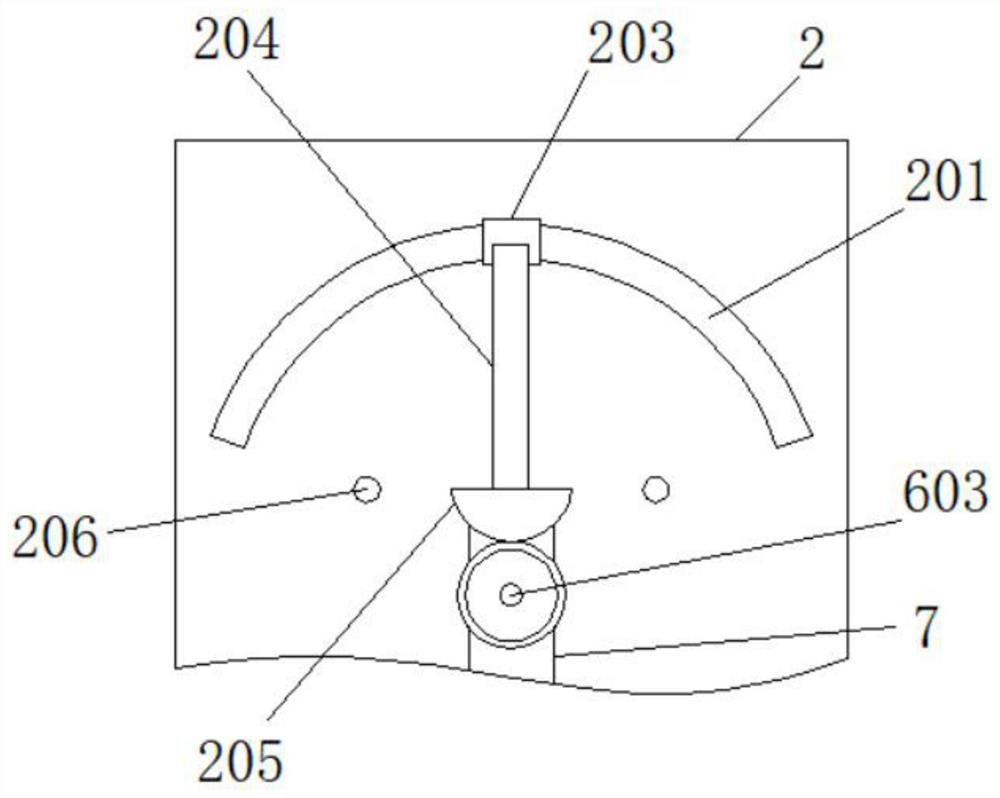
[0031] see Figure 1-6 , a detection device for cable processing, comprising a base 1, including a base 1 and a cable body 8, the top of the base 1 is respectively provided with a workbench 2 and a pay-off device 3, and the workbench 2 body is respectively provided with a No. 1 bushing 4, The top of the casing 5 and the No. 2 casing 6, the top of the pay-off device 3 is provided with a No. 1 fixed rod 301, the top of the No. 2 casing 6 is provided with a No. 2 fixed rod 601, and the top of the No. 1 fixed rod 301 is provided with a No. 1 gear 302, and the top of No. 2 fixed rod 601 is provided with No. 2 gear 602, No. 1 gear 302 and No. There is an arc-shaped chute 201, and the inside of the arc-shaped chute 201 is slidably connected with a slider 202, the top of the slider 202 is fixedly connected with a limit tube 203, and the top of the limit tube 203 is provided with an L-shaped plate 204, L-shaped The other end of the plate 204 is welded with a sector gear 205, and the s...

Embodiment 2

[0041] On the basis of Example 1, please refer to Figure 1-6 , a detection method for cable processing detection equipment, its use steps are as follows:

[0042] S1. First place the cable roller 305 on the base 304, pass the cable body 8 through the No. 1 casing 4, and use the laser sensor 406 to detect the surface smoothness and flatness of the cable body 8.

[0043] S2. Then the cable body 8 passes through the No. 2 through groove 503 on the left side of the box body 5 and enters the inside of the box body 5, so that the cable body 8 is covered on the surface of the guide wheel 502. By turning the No. 1 threaded rod 506, the pressure plate 507 compresses and limits the cable body 8 , and adjusts the height of the guide wheel 502 through the telescopic rod 501 , so as to detect the tensile capacity of the cable body 8 .

[0044] S3. When it is necessary to perform a breaking test on the cable body 8, move the cable body 8 from the inside of the box body 5 through the No. ...


PUM


Abstract

The invention discloses detection equipment for cable processing. The equipment comprises a pedestal and a cable body, and the top end of the pedestal is provided with a workbench and a pay-off device. Through the arrangement of a first sleeve and a box body, the flatness of the surface of the cable body and the tensile capacity of the cable body can be detected, when the motor drives the cable roller to rotate in a reciprocating manner, the first gear at the top end of the first fixing rod is driven to rotate in a reciprocating manner, and the first gear drives the second gear to rotate in areciprocating manner through the crawler belt, a third gear thus rotates in areciprocating manner, the third gear is engaged with the fan-shaped gear, the fan-shaped gear drives the cable body fixed in the limiting pipe to swing left and right in a reciprocating mode through the L-shaped plate, when the swinging cable body makes contact with detection photoelectricity, the number of swinging timesof the cable body can be known, and the cable can be subjected to a breaking test; the motor drives the cable roller to rotate in a reciprocating manner, and meanwhile, the cable body can be dragged.

Description

technical field [0001] The invention relates to the field of cable detection, in particular to a detection device for cable processing. Background technique [0002] Coaxial cable refers to a cable with two concentric conductors, and the conductor and shield share the same axis. The most common coaxial cable consists of copper conductors separated by insulating material, on the outside of the inner insulating material is another layer of ring conductor and its insulator, and then the whole cable is covered by a sheath of PVC or Teflon material . [0003] The coaxial cable detection equipment in the prior art has single functions, cannot be used continuously, has low detection efficiency and poor practicability. Contents of the invention [0004] Aiming at the deficiencies of the prior art, the present invention provides a detection device for cable processing, which has the advantages of multiple cable detection functions and solves the problems raised by the background ...

Claims


Application Information

Patent Timeline
IPC IPC(8): G01N3/08G01N3/20G01N3/04G01B11/30
CPCG01B11/30G01B11/306G01N3/04G01N3/08G01N3/20G01N2203/0017G01N2203/0023G01N2203/0067G01N2203/028
Inventor 陈启实
Owner 杭州艾特线缆有限公司
Why Eureka
Try Eureka