
A rainfall simulation system and method

A simulation system and rainfall box technology, applied in the field of engineering simulation, can solve the problems of affecting test results, less research and application, disturbance of rock and soil test models, etc., and achieve the effect of reliable test parameters

Active Publication Date: 2021-08-31
SOUTHWEST JIAOTONG UNIV
View PDF0 Cites 0 Cited by
  • Summary
  • Abstract
  • Description
  • Claims
  • Application Information

AI Technical Summary

Problems solved by technology

[0002] At present, because the nozzle-type rainfall device is highly automated and easy to control, scholars mostly use the nozzle-type rainfall device to study slope stability under different rainfall conditions; and the needle-tube artificial rainfall device is complicated in theory and difficult to control, so research There are few applications, and the traditional needle-shaped artificial rainfall devices mainly have the following disadvantages:
[0003] The traditional needle-shaped artificial rainfall device is connected to the rainfall box through a water supply pipe, and the bottom plate of the rainfall box is opened to install a needle to simulate rainfall. This form has a low degree of automation and cannot effectively control the start and stop of artificially simulated rainfall. The model generates disturbances that affect the test results
[0004] The control of the traditional needle-type rainfall device cannot control the opening and closing of the needle, so the adjustment of the rainfall intensity is a process of gradual change over time. It is difficult to express and analyze the rainfall intensity in the gradual change process with mathematical functions, resulting in large errors in the test results.
[0005] Most of the traditional needle-tube rainfall devices can only simulate rainfall in a single area, or simulate the same rainfall intensity in different areas, and cannot realize the independent rainfall function of different rainfall intensities in different regions of the rainfall box

Method used


Image

  • A rainfall simulation system and method
  • A rainfall simulation system and method
  • A rainfall simulation system and method

Examples


Embodiment Construction

[0030] In order to enable those skilled in the art to better understand the technical solutions in this specification, the technical solutions in the embodiments of this specification will be clearly and completely described below in conjunction with the drawings in the embodiments of this specification. Obviously, the described The embodiments are only some of the embodiments in this specification, not all of them. Based on the embodiments in this specification, all other embodiments obtained by persons of ordinary skill in the art without creative efforts shall fall within the protection scope of this specification.

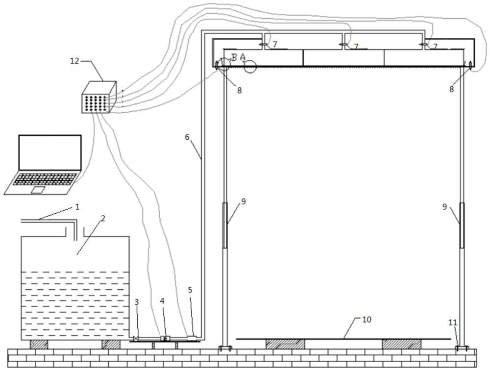
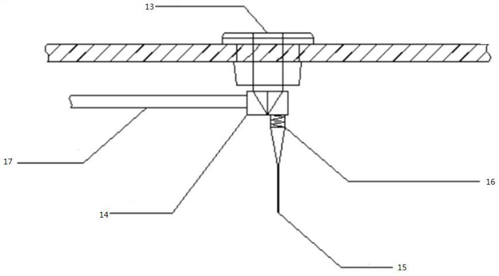
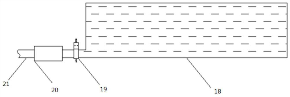
[0031] Such as Figure 1 to Figure 6 As shown, some embodiments of this specification provide a rainfall simulation system, including a rainfall device, and the rainfall device includes a partition rainfall box 18, a check valve 13, a diverter valve 14, and a rainfall needle 15; the check valve 13 is arranged in a partition At the bottom of the rain box 18, th...


PUM


Abstract

The invention discloses a rainfall simulation system and method. The system includes: a rainfall device, the rainfall device includes a partitioned rainfall box, a check valve, a diverter valve, and a rainfall needle; a water supply device, the water supply device includes a water inlet pipeline , a water pump, a water supply pipeline, a flow control valve; a control device, the control device is used to control the water supply device and the rainfall device. The invention can automatically control the opening and closing of the rainfall needle and the independent rainfall function of the partitioned rainfall box, and can accurately simulate the test conditions of stable, variable and uniform rainfall in multiple regions at the same time, and provide reliable test parameters for related research on geotechnical engineering and environmental engineering .

Description

technical field [0001] The invention relates to the technical field of engineering simulation, in particular to a rainfall simulation system and method. Background technique [0002] At present, because the nozzle-type rainfall device is highly automated and easy to control, scholars mostly use the nozzle-type rainfall device to study slope stability under different rainfall conditions; and the needle-tube artificial rainfall device is complicated in theory and difficult to control, so research There are few applications, and the traditional needle-shaped artificial rainfall devices mainly have the following disadvantages: [0003] The traditional needle-shaped artificial rainfall device is connected to the rainfall box through a water supply pipe, and the bottom plate of the rainfall box is opened to install a needle to simulate rainfall. This form has a low degree of automation and cannot effectively control the start and stop of artificially simulated rainfall. The model...

Claims


Application Information

Patent Timeline
Patent Type & Authority Patents(China)
IPC IPC(8): E03B1/00B05B9/04B05B12/08
CPCB05B9/0409B05B12/08E03B1/00
Inventor 杨长卫陈桂龙童心豪瞿立明王栋刘阳
Owner SOUTHWEST JIAOTONG UNIV
Learn More