
Piston ring clamping device with tidying function

A piston ring clamp and piston ring technology, which is applied in the direction of chucks, grinding machine parts, grinding feed movement, etc., can solve the problem that the operation stability of non-standard automatic processing equipment is greatly affected and the jaws are difficult to grasp , poor stability and other problems, to achieve the effect of reducing maintenance and repair costs, small contact area of ​​side clamping, and stable clamping

Pending Publication Date: 2021-03-16
安庆帝新机电设备有限公司
View PDF0 Cites 2 Cited by
  • Summary
  • Abstract
  • Description
  • Claims
  • Application Information

AI Technical Summary

Problems solved by technology

Due to the shape characteristics of the piston rings, the stability of the batch piston rings is poor after stacking neatly, and they are easy to be confused. It is difficult to grab the jaws and there are many faults, which has a great impact on the operation stability of non-standard automatic processing equipment.

Method used


Image

  • Piston ring clamping device with tidying function
  • Piston ring clamping device with tidying function

Examples


Embodiment 1

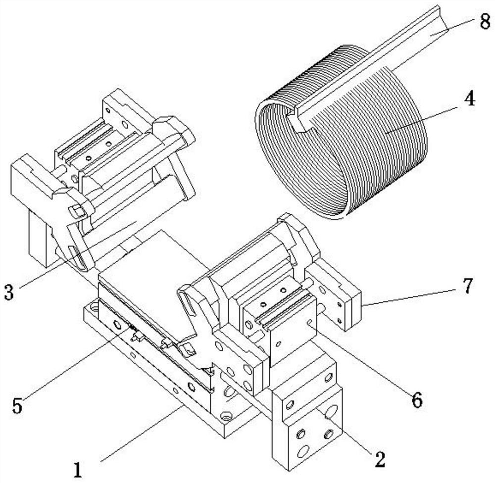
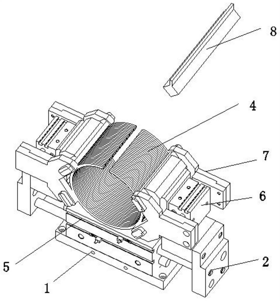
[0022] like Figure 1-2 As shown, a piston ring clamping device with finishing function, including a base 1,

[0023] The top of the base 1 is provided with a radial clamping mechanism, and the radial clamping mechanism is provided with an axial clamping mechanism;

[0024] The radial clamping mechanism includes two clamping seats 2, and a set of radial clamping plates 3 are arranged on the two clamping seats 2, which are symmetrically arranged, and the two radial clamping plates 3 are used for clamping batch piston rings 4;

[0025] A set of radial splints 3 is composed of two symmetrically arranged splints matched with the outer walls of the batch piston rings 4;

[0026] The batch of piston rings 4 is conveyed by an external conveying mechanism into the clamping regions of the radial clamping mechanism and the axial clamping mechanism.

[0027] The radial clamping mechanism includes an expanding and grasping cylinder 1 5, and the expanding and grasping cylinder 1 5 is a t...


PUM


Abstract

The invention provides a piston ring clamping device with a tidying function, and relates to the field of clamping devices. The piston ring clamping device comprises a base, a radial clamping mechanism is arranged at the top of the base, and an axial clamping mechanism is arranged on the radial clamping mechanism. According to the piston ring clamping device, standard universal parts are fully used for a clamping jaw to reduce mechanical structural parts, so that the maintenance cost is reduced; the clamping jaw conducts second-time clamping action in the radial clamping action, when a first expanding and grabbing air cylinder conducts clamping for the first time, the clamping force of the air cylinder is small clamping force set through an electric proportional valve, and damage to pistonring products is small; meanwhile, small gaps exist among batches of piston rings hung on a piston ring assembling and disassembling hanging rod, the piston rings are staggered, the clamping force issmall when a radial second expanding and grabbing air cylinder clamps the piston rings for the first time, the staggered piston rings can be tidied and clamped, after the axial first expanding and grabbing air cylinder clamps the piston rings in place, the small gaps among the piston rings are eliminated, and finally, the first expanding and grabbing air cylinder conducts second-time clamping with large clamping force.

Description

technical field [0001] The invention relates to the field of clamping devices, in particular to a piston ring clamping device with a sorting function. Background technique [0002] In the non-standard machine tool automatic processing equipment industry, there are many kinds of grippers for grasping workpieces. In the design of mechanical grippers for grasping small and medium-sized circular workpieces in batches, such as piston rings of automobile engines, the reliability of the grippers is stable. Sexual requirements are high. Due to the shape characteristics of the piston rings, the stability of batch piston rings is poor after being stacked neatly, and it is easy to be confused, the gripper is difficult to grasp, and there are many failures, which have a great impact on the running stability of non-standard automatic processing equipment. SUMMARY OF THE INVENTION [0003] The purpose of the present invention is to provide a piston ring clamping device with an arrangin...

Claims


Application Information

Patent Timeline
Patent Type & Authority Applications(China)
IPC IPC(8): B23Q7/04B24B41/00B25J15/02B25J15/00
CPCB23Q7/04B24B41/005B25J15/0028B25J15/0206
Inventor 胡荣庆洪瑞林
Owner 安庆帝新机电设备有限公司
Learn More