Bearing ring clamp

A technology for bearing rings and fixtures, which is applied in the field of bearing processing fixtures, can solve the problems of reduced turning accuracy, time-consuming and labor-intensive bearing rings, and low practicability, and achieve the effects of improving turning accuracy, increasing installation speed, and high practicability

Pending Publication Date: 2021-03-16
常熟缘阳机械制造有限公司
View PDF7 Cites 4 Cited by
  • Summary
  • Abstract
  • Description
  • Claims
  • Application Information

AI Technical Summary

Problems solved by technology

[0003] At present, although the bearing ring can be clamped by the clamping method, when the precision of the processed bearing ring is high, as long as the clamp clamps the outer edge surface of the bearing ring, the bearing ring will be slightly deformed. , it will lead to reduced turning accuracy and low practicability; and the current fixture cannot be rotated, which makes it time-consuming and laborious for workers to fix the bearing ring, and the installation speed is slow

Method used


Image

  • Bearing ring clamp
  • Bearing ring clamp
  • Bearing ring clamp

Examples


Embodiment Construction

[0019] The following will clearly and completely describe the technical solutions in the embodiments of the present invention with reference to the accompanying drawings in the embodiments of the present invention. Obviously, the described embodiments are only some, not all, embodiments of the present invention. Based on the embodiments of the present invention, all other embodiments obtained by persons of ordinary skill in the art without making creative efforts belong to the protection scope of the present invention.

[0020] Unless otherwise defined separately, directions such as up, down, left, right, front, back, inside and outside referred to herein are up, down, left, right, front and back in the drawings shown in the present invention. , inside and outside directions shall prevail, which shall be explained together here.

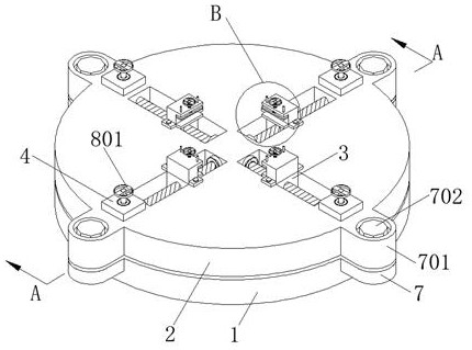
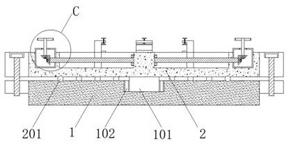
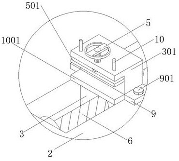
[0021] The present invention provides such Figure 1-4 A bearing ring fixture shown, including a base 1;

[0022] The center of the top of the bas...


PUM


Abstract

The invention discloses a bearing ring clamp. The bearing ring clamp comprises a base, wherein a mounting groove allowing a first bearing to be fixedly arranged is formed in the center of the top endof the base, a shaft rod is movably connected into the first bearing, and a movable seat is fixedly welded to the end, away from the base, of the shaft rod; the top end of the base and the bottom endof the movable seat are provided with annular grooves allowing rollers to slide, the top end of the movable seat is provided with two sets of rectangular sliding grooves allowing rectangular sliding blocks to slide in an annular array, the top end of the movable seat is provided with two sets of rectangular grooves in an annular array, and the top ends of the rectangular sliding blocks are fixedlyconnected with L-shaped fixing parts; and a threaded hole is formed in the center of one side of the top end of each L-shaped fixing part. According to the bearing ring clamp, the situation that a bearing ring is clamped from the outer edge face is avoided, deformation of the bearing ring is avoided, the turning precision is improved, the practicability is high, rotation can be conducted, time and labor are saved when workers fix the bearing ring, and the installation speed is improved.

Description

technical field [0001] The invention belongs to the technical field of bearing processing fixtures, and in particular relates to a bearing ring fixture. Background technique [0002] Bearing is an important part of contemporary mechanical equipment. Its main function is to support the mechanical rotating body, reduce the friction coefficient during its movement, and ensure its rotation accuracy. Bearings are divided into many categories, and rolling bearings are only one of them. Rolling bearings mainly include three parts: outer ring, inner ring, rolling elements and cages. In the production process of rolling bearings, the four parts are produced separately, and then the four parts are processed. Assemble. The inner and outer rings of rolling bearings are collectively referred to as bearing rings. In the production process of bearing rings, the inner and outer rings of bearing rings need to be turned, and the inner ring of bearing rings is generally turned with a jig Cla...

Claims


Application Information

Patent Timeline
Patent Type & Authority Applications(China)
IPC IPC(8): B23Q3/00
CPCB23Q3/00B23Q2703/10
Inventor 陈仪瞿宇聪李小华
Owner 常熟缘阳机械制造有限公司
Why Eureka
Try Eureka