Organic waste liquid recovery equipment and method thereof

A technology of organic waste liquid and recycling equipment, applied in organic chemistry, separation methods, chemical instruments and methods, etc., can solve problems affecting the quality of recycled products, decomposition of target components, and other reactions, so as to reduce decomposition or other reactions Probability of reaction, reduced residence time, reduced effect of connecting pipes

Pending Publication Date: 2021-03-16
湖南化工设计院有限公司
View PDF0 Cites 4 Cited by
  • Summary
  • Abstract
  • Description
  • Claims
  • Application Information

AI Technical Summary

Benefits of technology

This patented technology uses partial walls for separating different parts (targets) from each others during processing. By dividing this method into two sections - one concentrates some specific areas onto another area – it allows targets like protein or nucleic acid molecules to be separated effectively without having them mixed up together again after being collected by multiple tiers. Additionally, there're also included a system where all phases can come back down through an equal distribution channel before entering the main body of equipment. Overall, these technical features improve efficiency and reduce costs compared to traditional methods such as evaporation techniques used when purifying large amounts of liquids containing proteins or nucleotides.

Problems solved by technology

This patented technical problem addressed in this patents relates to improving efficient methods for recovering valuable materials such as neonate salts that can improve their performance when incorporation into batteries due to factors like environmental concerns associated with disposal issues caused by current processes involving organic chemicals.

Method used


Image

  • Organic waste liquid recovery equipment and method thereof
  • Organic waste liquid recovery equipment and method thereof
  • Organic waste liquid recovery equipment and method thereof

Examples


Embodiment 1

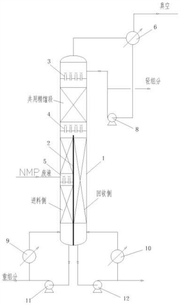
[0023] Such as Figure 2-3 As shown, this embodiment includes a dividing wall rectification column 1, which is divided into a feed side and a recovery side by a partition 2 in the dividing wall rectification column 1, and a third distributing device is provided on the feed side in the dividing wall rectification column 1. 5, a second distributor 4 is provided above the partition plate 2, a first distributor 3 is provided above the second distributor 4, and the common rectification section of the dividing wall rectification column 1 is located in the first distributor 3 and the second distributor 4. The main function of the common rectification section is to separate the target components from the light components, so that the content of light components in the liquid entering the feed side and recovery side is low.

[0024] The top of the next-wall rectification column 1 is connected to the input end of the first condenser 6 by a pipeline, and the output end of the first cond...

Embodiment 2

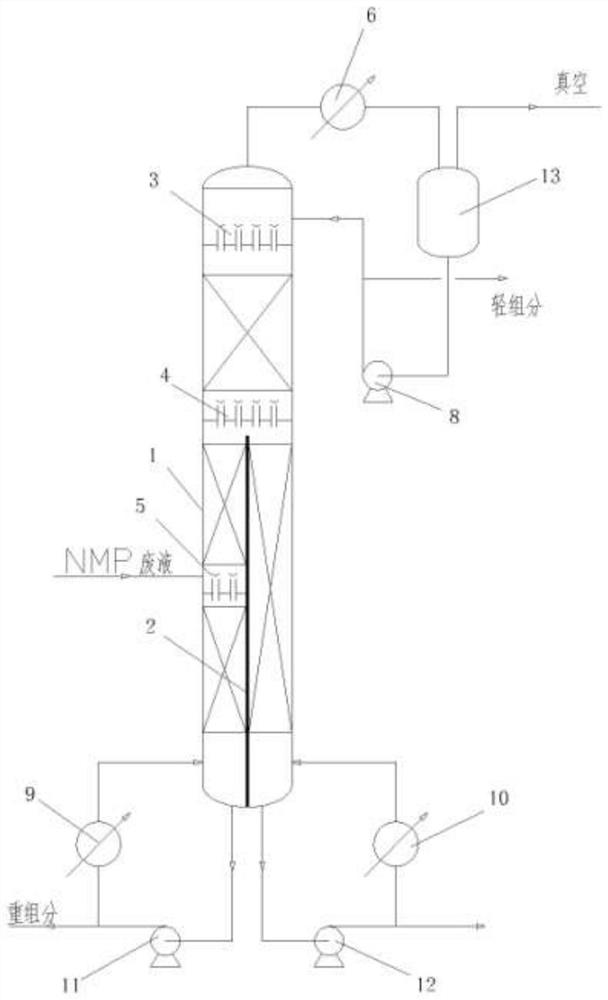
[0036] Such as Figure 4 As shown, the difference between this embodiment and embodiment 1 is that: the top of the rectifying column with dividing wall 1 is connected with two first condensers 6 and second condensers 7 connected in series through pipelines, and the output end of the first condenser 6 is passed through The pipes are respectively connected to the second condenser 7 and the upper part of the dividing wall rectification column 1 , and the second condenser 7 is connected to the top pump 8 . In this embodiment, all the condensate is returned to the next-door rectification column 1, and the vapor phase enters the second condenser 7 to condense and then enters the light component buffer tank 14, and then is output through the tower top pump 8.

[0037] In this embodiment, a vacuum buffer tank 15 connected to the light component buffer tank 14 may also be provided.

[0038] All the other are with embodiment 1.


PUM


Abstract

The invention relates to organic waste liquid recovery equipment and a method thereof, the organic waste liquid recovery equipment comprises a dividing wall rectifying tower, the dividing wall rectifying tower is divided into a feeding side and a recovery side by a partition plate, the feeding side is provided with a third distributor, a second distributor is arranged above the partition plate, afirst distributor is arranged above the second distributor, and the common rectifying section of the dividing wall rectifying tower is positioned between the first distributor and the second distributor. The invention further comprises the method for recycling the organic waste liquid by utilizing the dividing wall rectifying tower. A multi-tower process is combined into a single-tower process, sothat light components, heavy components and target components in the waste liquid are effectively separated, the number of rectifying towers and connecting pipelines are reduced, the process flow isshort, the investment is small, the retention time of the target components in the device is shortened, and the energy consumption is reduced by over 10 percent compared with that of a conventional rectifying scheme; and the probability of decomposition or other reactions of the target component is reduced.

Description


Claims


Application Information

Patent Timeline
Owner 湖南化工设计院有限公司
Why Eureka
Try Eureka