Ground cleaning device

A technology for ground cleaning and floor washing, applied in cleaning devices, cleaning equipment, cleaning machinery, etc., can solve the problems of large volume, occupied space, and high workstation height, and achieve the purpose of reducing occupied space, preventing water leakage, and reducing height and volume. Effect

Pending Publication Date: 2021-03-16
ZHEJIANG GUOZI ROBOT TECH
View PDF0 Cites 2 Cited by
  • Summary
  • Abstract
  • Description
  • Claims
  • Application Information

AI Technical Summary

Problems solved by technology

[0002] At present, when the existing washing robot runs to the workstation to add water, because the water inlet of the washing robot is set on the top of the water storage tank, the water supply port of the workstation needs to be located above the water inlet of the washing robot to realize the The function of aligning the water supply port with the water inlet and adding water to the water storage tank makes the workstation too high and bulky, taking up a lot of space

Method used


Image

  • Ground cleaning device
  • Ground cleaning device

Examples


Embodiment 1

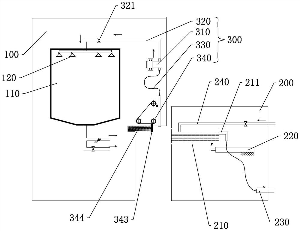
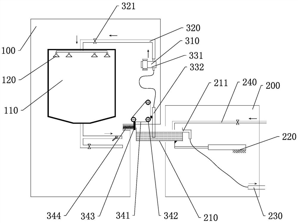
[0038] A floor cleaning device such as figure 1 and figure 2 As shown, it includes a scrubbing robot 100 and a workstation 200 that cooperates with the scrubbing robot 100. The scrubbing robot 100 moves on the ground for cleaning the ground. The workstation 200 is fixed. When the scrubbing robot 100 needs to perform operations such as adding water and charging, Just move the scrubbing robot 100 to the workstation 200 and connect with the workstation 200 . The workstation 200 in this embodiment includes a water supply tank 210 for providing clean water to the scrubbing robot 100. The scrubbing robot 100 includes a casing and a water storage tank 110 and a water adding assembly 300 disposed in the casing. The water adding assembly 300 is located in the water storage tank 110 On one side, the water adding assembly 300 includes a water pump 310, a water outlet pipe 320 located at the upper part of the water pump 310 and a water inlet pipe 330 located at the lower part of the wat...

Embodiment 2

[0048] In this embodiment, the water inlet pipe includes a bellows connected to the water pump and a water suction pipe connected to the lower end of the hose, the first drive mechanism is connected to the side of the water suction pipe, and the foldable corrugated sheet on the bellows makes the bellows have Scalable function, when the suction pipe retracts into the casing, the foldable corrugated sheet of the bellows is folded, and when the suction pipe extends out of the casing, the foldable corrugated sheet of the bellows unfolds to realize the expansion and contraction of the water inlet pipe , the structure is simple and easy to obtain, and the production cost is reduced.


PUM


Abstract

The invention discloses a ground cleaning device which comprises a ground cleaning robot and a work station, the work station comprises a water supply tank, the ground cleaning robot comprises a machine shell, a water storage tank and a water adding assembly, the water storage tank and the water adding assembly are arranged in the machine shell, and the water adding assembly is arranged on one side of the water storage tank; the water adding assembly comprises a water suction pump, a water outlet pipe located on the upper portion of the water suction pump and a water inlet pipe located on thelower portion of the water suction pump, and the water outlet pipe is connected with a water outlet of the water suction pump and the upper portion of the water storage tank, and the water inlet pipeis connected with the water inlet of the water suction pump, the water suction pump pumps liquid in the water supply tank through the water inlet pipe and conveys the liquid into the water storage tank through the water outlet pipe. The water adding assembly with the water suction pump is arranged on one side of the water storage tank, clear water in the water supply tank at the lower position canbe pumped to the upper portion of the water storage tank to be added into the water storage tank through pressurization of the water suction pump, a water supply structure of the workstation does notneed to be arranged to be higher than the water storage tank, and the height and size of the workstation are greatly reduced, and the footprint of a workstation is reduced.

Description

technical field [0001] The invention belongs to the field of cleaning equipment, and in particular relates to a floor cleaning device. Background technique [0002] At present, when the existing washing robot runs to the workstation to add water, because the water inlet of the washing robot is set on the top of the water storage tank, the water supply port of the workstation needs to be located above the water inlet of the washing robot to realize the The function of aligning the water supply port with the water inlet and adding water to the water storage tank makes the workstation too high and bulky, taking up a lot of space. Contents of the invention [0003] The technical problem to be solved by the present invention is to provide a floor cleaning device to solve at least one of the above problems. [0004] In order to solve the above-mentioned technical problems, the present invention adopts the following technical solutions: a ground cleaning device, including a scru...

Claims


Application Information

Patent Timeline
Patent Type & Authority Applications(China)
IPC IPC(8): A47L11/28A47L11/40
CPCA47L11/28A47L11/40A47L11/4091A47L11/4083A47L11/4063A47L2201/026A47L2201/00
Inventor 赖华敏翟瑾祁伟建
Owner ZHEJIANG GUOZI ROBOT TECH
Why Eureka
Try Eureka