Photovoltaic power generation device and power generation method thereof
A photovoltaic power generation, photovoltaic panel technology, applied in photovoltaic power generation, photovoltaic modules, solar thermal power generation and other directions, can solve the problems of low solar photovoltaic panel receiving light power generation rate, no photovoltaic panel cleaning dust, unable to adjust the sun in real time, etc. Practicality, improved stability, and improved light-receiving efficiency
- Summary
- Abstract
- Description
- Claims
- Application Information
AI Technical Summary
Problems solved by technology
Method used
Image
Examples
Embodiment 1
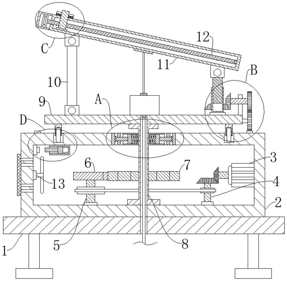
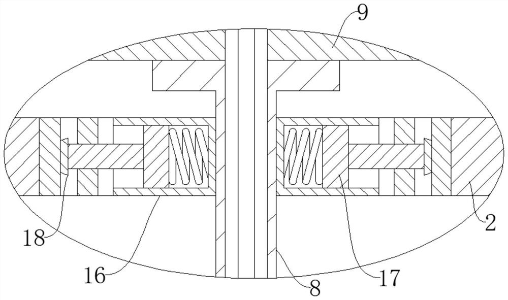
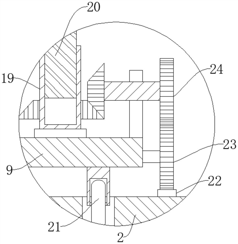
[0036] refer to Figure 1-9 , a photovoltaic power generation device, including a support base 1, an equipment box 2, a fixed frame 11, a photovoltaic panel body, the equipment box 2 is fixedly connected to the upper end of the support base 1, the photovoltaic panel body is fixedly connected in the fixed frame 11, and the equipment box 2 A driving reduction mechanism is connected inside, and the output end of the driving reduction mechanism is fixedly connected with a single-toothed gear 6, and the inside of the equipment box 2 is rotatably connected with a rotating rod 8, and the rotating rod 8 is fixedly connected with a first gear that matches the single-toothed gear 6 7. The equipment box 2 is provided with a through opening, and the upper end of the rotating rod 8 runs through the equipment box 2 through the through opening, and is fixedly connected with a support plate 9, and the upper end side of the support plate 9 is rotationally connected with a fixed rod 10, and on t...
Embodiment 2
[0039] refer to figure 1 with Figure 8 , a photovoltaic power generation device, which is basically the same as that of Embodiment 1, furthermore: the drive reduction mechanism includes a reduction motor 3, a first rotating shaft 4, and a second rotating shaft 5, and the reduction motor 3 is fixedly connected to one side of the equipment box 2, The first rotating shaft 4 and the second rotating shaft 5 are both rotationally connected to the equipment box 2, the output end of the reduction motor 3 is fixedly connected with a driving bevel gear, and the second rotating shaft 5 is fixedly connected with a driven bevel gear matching the driving bevel gear, The size of the driven bevel gear is twice that of the driving bevel gear. The first rotating shaft 4 and the second rotating shaft 5 are fixedly connected with pulleys. The two pulleys are connected by a belt. The single-toothed gear 6 is fixedly connected to the second rotating shaft 5. When the sun rises, the deceleration m...
Embodiment 3
[0041] refer to image 3 , a photovoltaic power generation device, which is basically the same as Embodiment 1, furthermore: the drive mechanism includes a second gear 23, a third gear 24, the second gear 23 is rotatably connected to the support plate 9, the second gear 23 is connected to the ring The racks 22 are meshed, and the end of the support plate 9 near the cylinder 19 is fixedly connected with a fixed plate, and the fixed plate is rotatably connected with a rotating column, and the end of the rotating column away from the cylinder 19 is fixedly connected with the third gear 24, and the second gear 23 Engaged with the third gear 24, the end of the rotating column away from the third gear 24 is fixedly connected with a second bevel gear, the second bevel gear is engaged with the first bevel gear, wherein the second gear 23 is in engagement with the ring rack 22, When the support plate 9 rotates, under the action of the ring rack 22, the second gear 23 will follow the ro...
PUM
 Abstract
Description
Claims
Application Information
 - R&D
- Intellectual Property
- Life Sciences
- Materials
- Tech Scout
- Unparalleled Data Quality
- Higher Quality Content
- 60% Fewer Hallucinations
Browse by: Latest US Patents, China's latest patents, Technical Efficacy Thesaurus, Application Domain, Technology Topic, Popular Technical Reports.
© 2025 PatSnap. All rights reserved.Legal|Privacy policy|Modern Slavery Act Transparency Statement|Sitemap|About US| Contact US: help@patsnap.com


