Transmitting and receiving wavelength matching method for laser radar

A technology of wavelength matching and laser radar, which is applied in the field of laser radar detection, can solve the problems of high difficulty of narrow-band filter technology and increase the difficulty of laser radar system wavelength matching, etc., achieve real-time automatic matching, large laser damage threshold, and improve practicality sexual effect

Active Publication Date: 2021-03-12
INST OF OPTICS & ELECTRONICS - CHINESE ACAD OF SCI
View PDF22 Cites 0 Cited by
  • Summary
  • Abstract
  • Description
  • Claims
  • Application Information

AI Technical Summary

Problems solved by technology

[0002] When working under strong background light conditions, the laser radar system needs to perform spectral filtering, so it is necessary to find a narrow-band filter that matches the center wavelength of the laser emission. In practice, the process of narrow-band filters is relatively difficult, which greatly increases the transmission and reception of the laser radar system. The difficulty of wavelength matching

Method used


Image

  • Transmitting and receiving wavelength matching method for laser radar

Examples


Embodiment Construction

[0022] The following will clearly and completely describe the technical solutions in the embodiments of the present application with reference to the accompanying drawings in the embodiments of the present application. Obviously, the described embodiments are only part of the embodiments of the present application, not all of them. Based on the embodiments in this application, all other embodiments obtained by persons of ordinary skill in the art without making creative efforts belong to the scope of protection of this application.

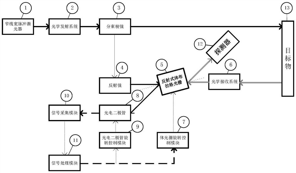
[0023] like figure 1 As shown, the present invention is a method for laser radar transceiver wavelength matching, figure 1 The solid black arrow is the outgoing light, the gray arrow is the echo light, the black dotted arrow is the electrical signal, and the gray dotted line is the volume grating normal. A method for laser radar transceiver wavelength matching, comprising a narrow linewidth pulse laser ①, an optical transmitting system ②, a beam ...


PUM

PropertyMeasurementUnit
Spectral widthaaaaaaaaaa

Abstract

The invention discloses a transmitting and receiving wavelength matching method for a laser radar. A narrow-linewidth pulse laser, an optical transmitting system, a beam splitter prism, a reflector, areflective volume Bragg grating, an optical receiving system, a volume grating rotation control module, a photodiode, a photodiode rotation control module, a signal acquisition module, a signal processing module and a detector are included. The method can achieve the matching of the central wavelengths of the transmitting system and the receiving system of the laser radar. Bragg diffraction anglecharacteristics of the two surfaces of the volume Bragg grating are respectively utilized, and the reference light after beam splitting and the signal light received by the receiving system respectively enter the two surfaces, so that Bragg diffraction occurs simultaneously at the same angle, and the effect of matching the central wavelengths of a transmitted signal and a received signal is achieved. The method is particularly suitable for a laser radar system which works for a long time or uses a tunable laser.

Description

technical field [0001] The invention relates to lidar detection under long-distance strong background light, in particular to a method for matching the emission and reception wavelengths of the lidar. Background technique [0002] When working under strong background light conditions, the laser radar system needs to perform spectral filtering, so it is necessary to find a narrow-band filter that matches the center wavelength of the laser emission. In practice, the narrow-band filter process is relatively difficult, which greatly increases the laser radar system. The difficulty of wavelength matching. [0003] The reflective volume grating has an extremely narrow filtering bandwidth, and when its Bragg diffraction conditions are met, it can filter out most of the light other than the central wavelength. [0004] The reflective volume grating has good stability, has a very high laser damage threshold, and its diffraction has a certain angle characteristic, which can realize t...

Claims


Application Information

Patent Timeline
IPC IPC(8): G01S17/02G01S7/481G01S7/484G01S7/486
CPCG01S17/02G01S7/481G01S7/484G01S7/486Y02A90/10
Inventor 刘博范伟廖胜蒋赟
Owner INST OF OPTICS & ELECTRONICS - CHINESE ACAD OF SCI
Why Eureka
Try Eureka