Conveyor with automatic sorting function
An automatic sorting and conveyor technology, applied in the field of conveyors, can solve the problems of inconvenient removal of goods, wear of conveyor racks, slow speed, etc., and achieve the effect of realizing assembly line production, increasing use functions, and increasing service life.
- Summary
- Abstract
- Description
- Claims
- Application Information
AI Technical Summary
Problems solved by technology
Method used
Image
Examples
Embodiment 1
[0029] see Figure 1-Figure 7, the present invention provides a conveyor with automatic sorting function; a conveyor with automatic sorting function, comprising a base 1, a support frame 2 is fixedly installed at the lower end of the base 1, and a conveyor belt is fixedly installed above the base 1 3. An identification plate 5 is fixedly installed in the middle of the conveyor belt 3, a separation roller 7 is fixedly installed on the upper surface of the identification plate 5, a conveyor frame 6 is fixedly installed on the outside of the conveyor belt 3, and a collection box 10 is fixedly installed on the outside of the conveyor frame 6. The front end of the box 10 is fixedly equipped with a rotating plate 9, the top of the front surface of the rotating plate 9 is fixedly equipped with a handle 8, the left side of the conveyor belt 3 is fixedly installed with a fixed frame 4, and the top of the left surface of the collection box 10 is fixedly installed with an extension block ...
Embodiment 2
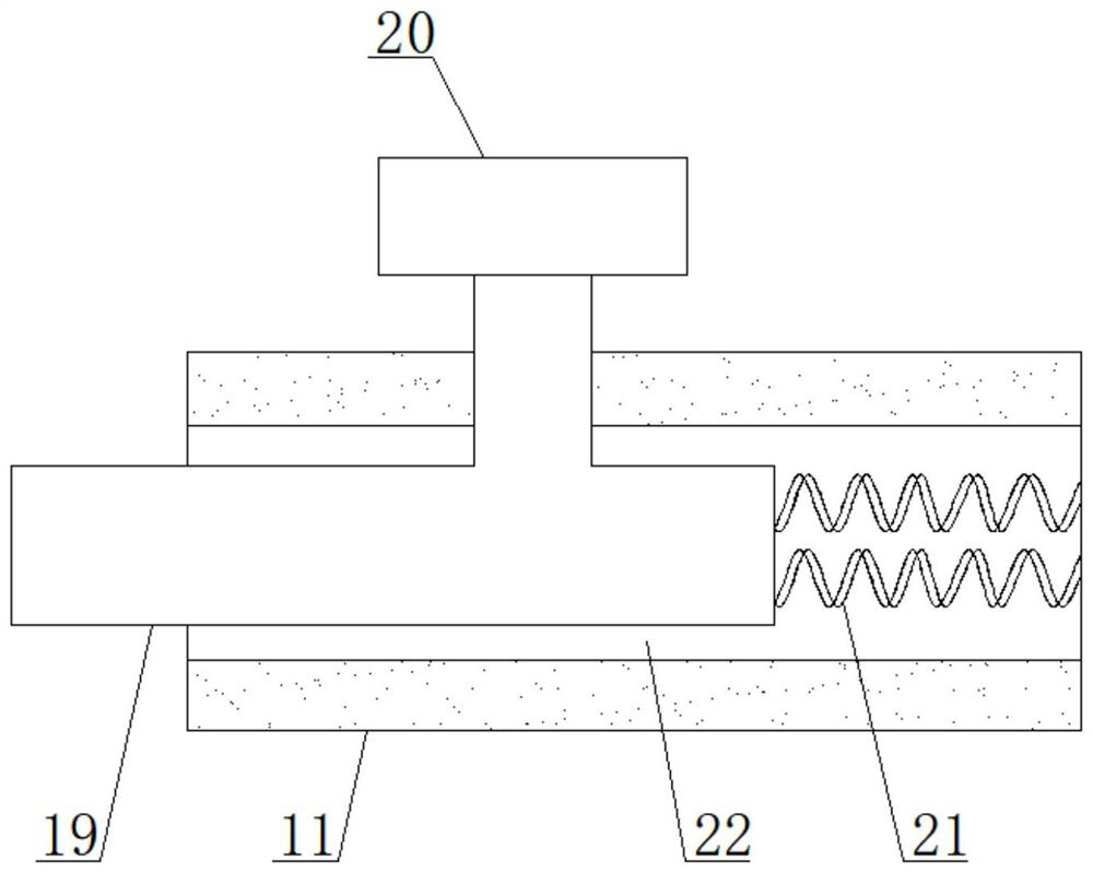
[0032] see figure 2 and image 3 , the upper surface of the extension block 11 is provided with a chute 22, the inside of the chute 22 is fixedly equipped with an adjustment button 20, the left end of the adjustment button 20 is fixedly installed with a limit column 19, and the right end of the adjustment button 20 is fixedly installed with a first spring 21, The top of the left and right outer surfaces of the rotating plate 9 is provided with a fixing hole 17, and the left and right outer surfaces of the collecting box 10 are provided with a through hole 14, and the rotating plate 9 and the collecting box 10 are fixed by a limit post 19, a through hole 14 and a fixing hole 17. Connection, the bottom of the rotating plate 9 is fixedly equipped with a hinge 16, and the other end of the hinge 16 is fixedly connected with the bottom front end of the collection box 10. There are three sets of hinges 16, and the rotating plate 9 and the collection box 10 are connected by three com...
Embodiment 3
[0035] see figure 1 , Figure 6 and Figure 7 , the corner of the lower surface of the fixed frame 4 is fixedly equipped with a telescopic sleeve rod 30, the middle part of the telescopic sleeve rod 30 is fixedly installed with a limit block 32, the upper end of the buffer column 31 is fixedly installed with a bearing plate 33, and the upper end of the load bearing plate 33 is fixedly installed There are inclined fabric buckets 34, and several groups of buffer columns 31 are arranged. The top of each group of buffer columns 31 is fixedly connected with the lower surface of the bearing plate 33, and the bottom of each group of buffer columns 31 is fixedly connected with the upper surface of the fixed frame 4. The buffer column 31 comprises a second spring 35, an upper buffer block 36, a first connection block 37, a second connection block 40, a dislocation sleeve 38 and a lower buffer block 39, and the top of the buffer column 31 is fixedly equipped with an upper buffer block ...
PUM
 Abstract
Description
Claims
Application Information
 - R&D Engineer
- R&D Manager
- IP Professional
- Industry Leading Data Capabilities
- Powerful AI technology
- Patent DNA Extraction
Browse by: Latest US Patents, China's latest patents, Technical Efficacy Thesaurus, Application Domain, Technology Topic, Popular Technical Reports.
© 2024 PatSnap. All rights reserved.Legal|Privacy policy|Modern Slavery Act Transparency Statement|Sitemap|About US| Contact US: help@patsnap.com


